[0019] In order to make the technical means, creative features, objectives and effects of the present invention easy to understand, the present invention will be further explained below in conjunction with specific embodiments.
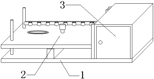
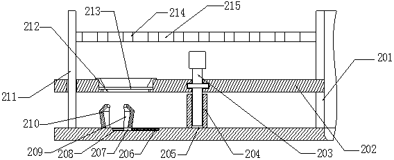
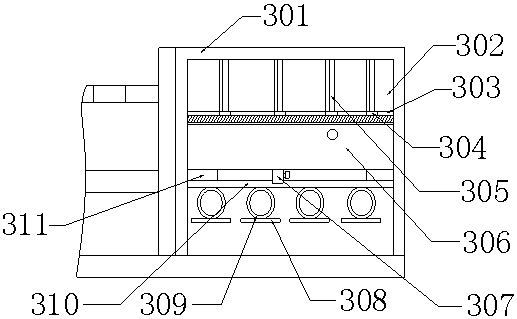
[0020] See Figure 1-Figure 3 , The present invention provides a technical solution: a safe and convenient biochemistry experiment device, including a bottom plate 1, a fixed component 2 and a storage component 3. The fixed component 2 is installed on the upper end surface of the bottom plate 1, and the storage component 3 is arranged on the right side of the fixed component 2. On the upper end surface of the bottom plate 1, the fixed assembly 2 includes a limit bar 201, a carrier plate 202, a screw 203, a fixed table 204, a threaded hole 205, a spring 206, a slider 207, a sliding groove 208, a movable splint 209, a fixed splint 210, Guide rod 211, counterbore 212, asbestos net 213, carrier rod 214 and ring 215, storage assembly 3 includes storage box 301, medicine storage room 302, strip groove 303, moving block 304, partition 305, water tank 306, The drain pipe 307, the pressure plate 308, the spring plate 309, the cross bar 310 and the fixed boss 311.
[0021] In the fixing assembly 2, the limit bar 201 is fixed on the left side of the storage box 301, the limit bar 201 is equipped with a limit block, the right end of the carrier plate 202 is connected with the limit block, and the left end of the carrier plate 202 is assembled on the guide rod 211 On the ring-shaped side surface, a guide rod 211 is fixed symmetrically on the left side of the upper end surface of the bottom plate 1. The fixing table 204 is installed at the middle position of the upper end surface of the bottom plate 1, and the middle position of the upper end surface of the fixing table 204 is machined with a threaded hole 205. 203, the upper end of the screw 203 is assembled at the middle position of the carrier plate 202, the upper end of the carrier plate 202 is provided with a counterbore 212 at the left position, the asbestos net 213 is installed inside the counterbore 212, and the upper end surface of the bottom plate 1 under the counterbore 212 A fixed splint 210 is fixed. The upper end surface of the bottom plate 1 on the right side of the fixed splint 210 is provided with a sliding groove 208. The sliding groove 208 is equipped with a sliding block 207. The upper end surface of the sliding block 207 is fixed with a movable splint 209. The spring 206 is installed in the sliding groove 208 On the inner right side, the left end of the spring 206 is connected to the right side of the slider 207, the rear end of the carrier rod 214 is fixed on the left side of the storage box 301, the left end of the carrier rod 214 is connected to the right end of the annular side of the guide rod 211, and the ring 215 is fixed on the carrier The front end of the rod 214.
[0022] In the storage assembly 3, the storage box 301 is fixed at the right ridge line of the upper end surface of the carrier board 202, the medicine storage room 302 is opened at the upper end of the inside of the storage box 301, and the lower side of the medicine storage room 302 is provided with a strip groove 303. The groove 303 is equipped with a moving block 304. The upper end of the moving block 304 is fixed with a partition 305. The upper side of the partition 305 is attached to the upper side of the medicine storage chamber 302. The fixed boss 311 is fixed on the lower side of the medicine storage chamber 302. On the inner wall of the storage box 301, a water tank 306 is fixed on the upper end of the fixed boss 311, a drain pipe 307 is installed at the front of the lower end of the water tank 306, and a cross bar 310 is fixed inside the storage box 301 on the lower side of the fixed boss 311. A spring piece 309 is installed on the end surface, and a pressure plate 308 is connected to the lower end of the spring piece 309.
[0023] As an embodiment of the present invention, a circular hole is provided in the middle of the upper end surface of the carrier plate 202, the upper end of the screw 203 is fitted inside the circular hole, the circular side of the circular hole is provided with an annular groove, and the annular groove is equipped with an annular boss. The annular boss is fixed on the annular side of the screw 203, and the upper end of the screw 203 is fixed with a handle. In actual use, place the alcohol lamp on the left end of the bottom plate 1, and place the trash box on the upper end of the bottom plate 1 on the right side of the fixed boss 311. During the experiment, adjust the height of the carrier plate 202 according to the heating temperature. When adjusting, turn the handle and turn the handle to drive the screw 203 to move inside the threaded hole 205, so that the screw 203 moves up and down, and the screw 203 moves through the annular boss to drive the carrier plate 202 moves, so that the carrier board 202 moves along the guide rod 211 and the limit bar 201. When the carrier board 202 moves to a suitable position, stop rotating the screw 203, which is convenient for adjusting the height of the carrier board 202, thereby realizing the adjustment of the heating temperature .
[0024] As an embodiment of the present invention, the left surface of the fixed splint 210 and the left surface of the movable splint 209 are both fixed with elastic rubber pads, and the countersunk hole 212 on the upper side of the asbestos net 213 is installed with a support frame. In actual use, the size A suitable support frame is assembled on the asbestos net 213, and the beaker to be heated is placed inside the support frame. The lower side of the beaker is attached to the upper side of the asbestos net 213, and then the moving splint 209 is pulled to the left, and the moving splint 209 moves and drives the slide The block 207 moves inside the chute 208, and the movement of the slider 207 generates a compressive force on the spring 206, which causes the spring 206 to contract. When the moving splint 209 moves to a suitable position, the alcohol lamp is placed on the upper end surface of the bottom plate 1 on the right side of the fixed splint 210 , And make the left side of the alcohol lamp fit the right side of the fixed splint 210, and then release the moving splint 209. Under the elastic force of the spring 206 to restore the deformation, the slider 207 drives the moving splint 209 to move to the left, thereby fitting on The left side of the alcohol lamp realizes the fixation of the alcohol lamp, improves the stability of the alcohol lamp and the beaker during the heating process, and has good safety.
[0025] As an embodiment of the present invention, there are two or more partitions 305, and the two or more partitions 305 are all connected to the strip groove 303 through a moving block 304, and the left side of the two or more partitions 305 is fixed with a sponge pad 2. In the actual use process, different chemical reagents are placed inside the storage chamber 302, and separated by the partition 305, and the partition 305 is pushed during storage, and the partition 305 moves and drives the moving block 304 in the strip groove 303 Internal movement, when the partition 305 is moved to a suitable position, just stop moving the partition 305, which is convenient for the classification and isolation of chemical agents.
[0026] As an embodiment of the present invention, the water tank 306 is provided with a water filling port on the upper surface of the front end, a sealing plug is installed inside the water filling port, a water valve is installed on the drain pipe 307, and the cross bar 310 is provided with more than two cross bars. 310 is arranged equidistantly at the lower end of the storage box 301. Two or more cross bars 310 are connected to two or more pressure plates 308 through spring sheets 309, and the lower end of the pressure plate 308 is fixed with a sponge pad 3. In actual use, through the water inlet Add a clean water flow to the water tank 306, and then open the water valve, and the clean water flow is discharged through the drain pipe 307 to clean the experimental equipment. When the beaker is placed, the pressure plate 308 is pushed upward, and the pressure plate 308 moves to produce a compression force on the spring plate 309, so that The spring plate 309 is deformed. When the pressing plate 308 moves to a suitable height, the beaker is placed on the lower side of the pressing plate 308, and the pressing plate 308 is released. Under the elastic force of the spring plate 309 to restore the deformation, it moves downward and fits on the upper side of the beaker. , Realize the fixation of the beaker, easy to clean and fix the beaker.
[0027] The above shows and describes the basic principles and main features of the present invention and the advantages of the present invention. For those skilled in the art, it is obvious that the present invention is not limited to the details of the above exemplary embodiments, and does not deviate from the spirit or basics of the present invention. In the case of features, the present invention can be implemented in other specific forms. Therefore, from any point of view, the embodiments should be regarded as exemplary and non-limiting. The scope of the present invention is defined by the appended claims rather than the foregoing description, and therefore it is intended to fall within the claims. All changes within the meaning and scope of equivalent elements of are included in the present invention.
[0028] In addition, it should be understood that although this specification is described in accordance with the embodiments, not every embodiment only includes an independent technical solution. This narration in the specification is only for clarity, and those skilled in the art should consider the specification as a whole The technical solutions in the embodiments can also be appropriately combined to form other implementations that can be understood by those skilled in the art.