Embedded floating underwater in-situ remediation device and mounting method thereof

An in-situ repair and floating device technology, which is applied to biological treatment devices, chemical instruments and methods, and water pollutants, can solve the problems of broken floating airbags, complex structures, and failure to perform in-situ repairs. The scope is expanded, the structure design is simple, and the water purification effect is improved.

Inactive Publication Date: 2018-06-15
中运建设控股有限公司
View PDF4 Cites 1 Cited by
  • Summary
  • Abstract
  • Description
  • Claims
  • Application Information

AI Technical Summary

Problems solved by technology

For the in-situ repair that people often use for such pollution, a series of underwater in-situ repair devices have been produced, but the existing underwater in-situ repair has a complicated structure, and some require a long pipeline to transport the sterilizing liquid. It is very inconvenient and inflexible; in addition, some existing solid bacterial agents are directly placed in water, which leads to fast dissolution and dispersion of solid bacterial agents in water, short use time, poor water purification effect, and does not play the original role. In addition, the floating airbag of the in-situ repair device is easily damaged by external sharp objects, which interrupts the operation

Method used


Image

  • Embedded floating underwater in-situ remediation device and mounting method thereof
  • Embedded floating underwater in-situ remediation device and mounting method thereof
  • Embedded floating underwater in-situ remediation device and mounting method thereof

Examples


Embodiment 1

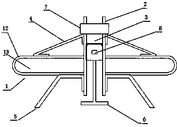
[0031] Such as figure 1 and 2 As shown, an embedded floating underwater in-situ restoration device includes a floating device 1 , a water inlet pipe 2 , a water purification core 3 , a water suction pump 7 , and an agitating device 8 . The floating device 1 has a ring structure, and the middle of the floating device 1 is a piercing hole 11, and the piercing hole 11 is used for inserting the water inlet pipe 2. The water inlet pipe 2 vertically runs through and connects with the middle of the floating device 1, and the water inlet pipe 2 has a cylindrical pipe body structure. The upper end of the water inlet pipeline 2 is equipped with a water suction pump 7, and the water suction pump 7 can suck the water in the water inlet pipeline 2 lower ends and then spray from the upper end of the water inlet pipeline 2. The water purification core 3 is installed in the water inlet pipe 2 inside. The water purification core 3 has blocked the cross section of the water inlet pipe 2, so ...

Embodiment 2

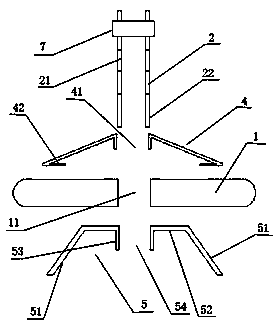
[0035] This embodiment refers to Embodiment 1, the difference is that this embodiment also includes an upper connection cover 4 and a lower limit cover 5 . Such as figure 1 and 2 As shown, the upper connection cover 4 and the lower limit cover 5 both have a ring structure. There is an insertion channel 41 in the middle of the upper connection cover 4 . The middle of the lower limit cover 5 is provided with an internal thread channel 54 . The outside of the lower end of the water inlet pipe 2 is provided with an external thread section 22 . The upper connection cover 4 is plugged into the outer surroundings of the water inlet pipe 2 through the plugging channel 41 . The upper connection cover 4 is installed between the floating device 1 and the water suction pump 7 . The upper end of the upper connection cover 4 abuts against the lower end of the water suction pump 7 . The lower end of the upper connection cover 4 abuts against the upper end of the floating device 1 . Th...


PUM


Abstract

The invention discloses an embedded floating underwater in-situ remediation device and a mounting method thereof. The embedded floating underwater in-situ remediation device comprises a floating device, a water diving pipeline, a water purification core, a water suction pump and a stirring device; the stirring device is mounted inside a lower tank body; the stirring device comprises a driving motor, a rotating shaft and stirring supports; the driving motor is mounted on the outer side wall of the lower tank body; the driving motor controls the rotating shaft to rotate; the rotating shaft is mounted inside the lower tank body; the outer side of the rotating shaft is provided with the plurality of stirring supports; the floating device comprises an inner air sac and an outer ring sleeve; theinner air sac is of an annular structure; the outer ring sleeve is of a ring body structure; the inner side of the outer ring sleeve is opened, and an annular cavity is formed inside the outer ring sleeve; and the inner air sac is mounted inside the annular cavity of the outer ring sleeve. The inner air sac disclosed by the invention can be protected by the outer ring sleeve, so that the risk that the air sac is damaged is avoided, and meanwhile, the water purification efficiency is greatly increased.

Description

technical field [0001] The invention relates to an embedded floating underwater in-situ repair device and an installation method thereof. Background technique [0002] With the rapid development of the human economy, more and more garbage is produced in production and life. The garbage in the garbage dump penetrates into the ground and pollutes the groundwater. In addition, the water in the lake is also polluted, mainly ammonia, Nitrogen compounds and organic pollution. For the in-situ repair that people often use for such pollution, a series of underwater in-situ repair devices have been produced, but the existing underwater in-situ repair has a complicated structure, and some require a long pipeline to transport the sterilizing liquid. It is very inconvenient and inflexible; in addition, some existing solid bacterial agents are directly placed in water, which leads to fast dissolution and dispersion of solid bacterial agents in water, short use time, poor water purificati...

Claims


Application Information

Patent Timeline
Patent Type & Authority Applications(China)
IPC IPC(8): C02F3/34C02F101/16C02F101/30
CPCC02F3/34C02F2101/16C02F2101/30C02F2203/006
Inventor 徐洪徐其泽
Owner 中运建设控股有限公司
Why Eureka
Try Eureka