
Rotating pore plate flow metering device

A technology of metering flow and rotating orifice plate, which is applied to the volume/mass flow rate generated by mechanical effects, and the detection of fluid flow by measuring differential pressure.

Pending Publication Date: 2018-06-15
北京大漠石油工程技术有限公司
View PDF6 Cites 5 Cited by
  • Summary
  • Abstract
  • Description
  • Claims
  • Application Information

AI Technical Summary

Problems solved by technology

[0003] The change of the flow range of the metering pipeline is a situation often encountered in actual use, especially when the flow rate increases beyond the upper limit of the flowmeter’s range, resulting in the operation of the differential pressure transmitter over the range, and the metering device cannot measure the flow rate accurately
At present, there are many ways to solve the above problems, such as combining large flow segments in parallel with multiple channels, changing the orifice plate to change the β value for measurement, and using an orifice plate flowmeter in parallel to connect differential pressure gauges with different ranges for measurement, but each technology is different. It has its own limitations and deficiencies. It needs to configure a large number of primary devices or secondary detection instruments to combine the large flow segmented multi-channel parallel connection and use an orifice flowmeter in parallel to connect different range differential pressure gauges. The technical cost is high, and the replacement of the hole The measurement of the plate changing the β value is only suitable for a long period of time when the seasonal flow rate changes greatly or the sudden change of the flow rate causes the differential pressure gauge to exceed the specified range of use, and some working conditions do not have the conditions to replace the orifice plate at all.

Method used


Image

  • Rotating pore plate flow metering device
  • Rotating pore plate flow metering device
  • Rotating pore plate flow metering device

Examples


Embodiment Construction

[0023] It should be noted that, in the case of no conflict, the embodiments in the present application and the features in the embodiments can be combined with each other. The present invention will be described in detail below with reference to the accompanying drawings and examples.

[0024] It should be pointed out that the following detailed description is exemplary and intended to provide further explanation to the present application. Unless defined otherwise, all technical and scientific terms used herein have the same meaning as commonly understood by one of ordinary skill in the art to which this application belongs.

[0025] In the present invention, unless stated otherwise, the used orientation words such as "upper, lower, top, bottom" are usually for the directions shown in the drawings, or for the parts themselves in the vertical, In terms of vertical or gravitational direction; similarly, for the convenience of understanding and description, "inner and outer" re...


PUM


Abstract

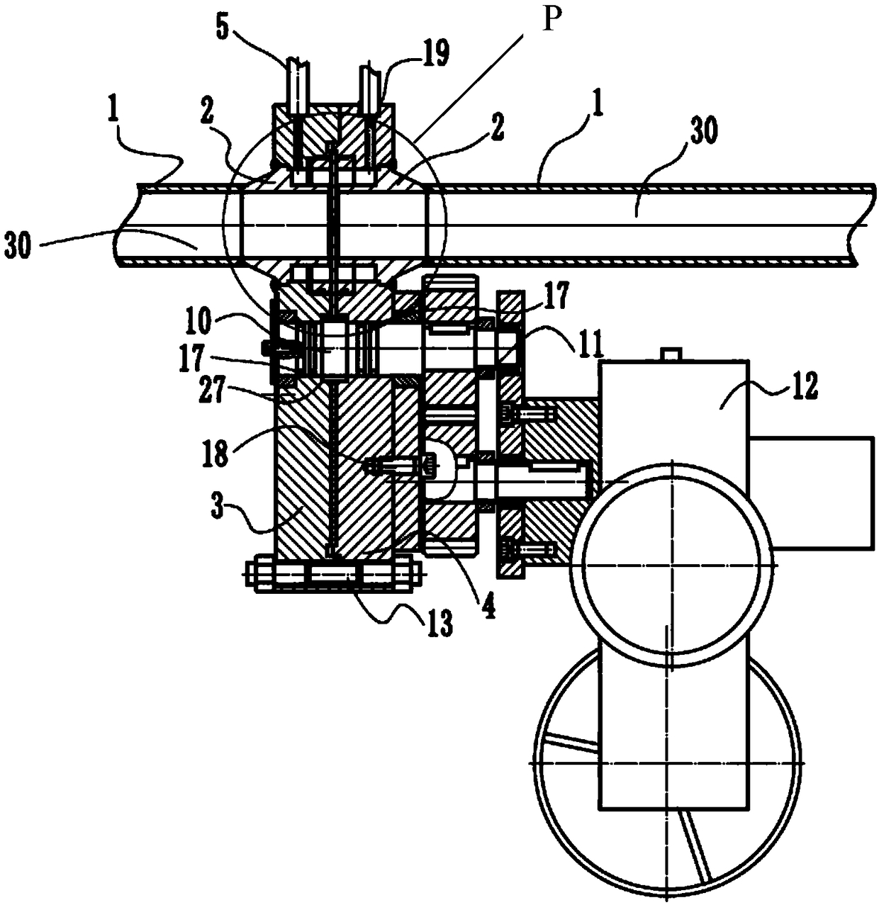
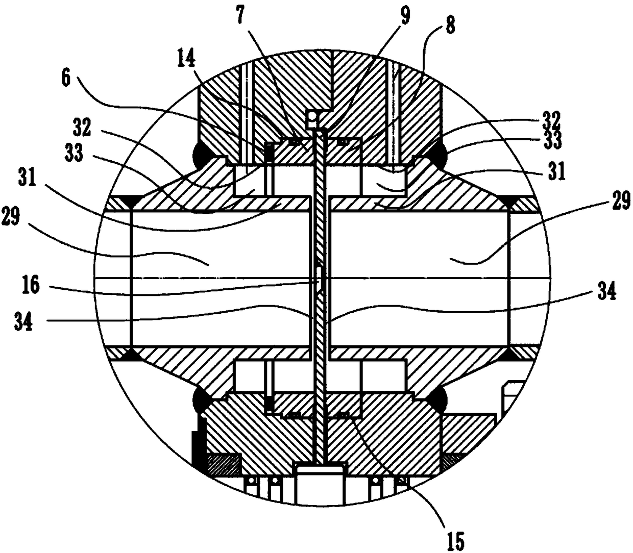
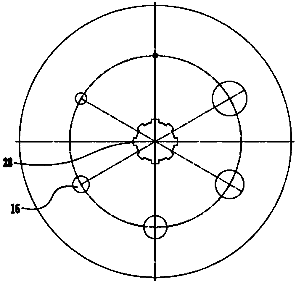
The invention provides a rotating pore plate flow metering device. The edge of a left clamping plate and the edge of a right clamping plate are connected together through a stud, two connecting pipesare installed on the cut-off portion of a straight pipe section and welded to the straight pipe section, and a gap is formed in the butt joint of the two connecting pipes. A round pore plate body is arranged in the gap between the two connecting pipes, the center of the pore plate body coincides with the center of a rotating shaft, the rotating shaft is sleeved with the pore plate body, the pore plate body is driven by the rotating shaft to rotate, and multiple throttling holes with different calibers are further evenly formed in the pore plate body at intervals in the circumferential direction. In the rotating process, the axes of the throttling holes coincide with the axes of the connecting pipes. A pressure difference is formed on the two sides of the throttling holes of the pore platebody by a measuring medium, a driver drives the pore plate body to rotate through a gearbox and the rotating shaft, the throttling holes with different calibers in the pore plate body are switched tobe sequentially located in a measuring pipeline, the measuring device is provided with the throttling holes with different beta values, and the device has a wider range ratio.

Description

technical field [0001] The invention relates to a differential pressure device installed in a circular cross-section pipeline to measure the fluid flow of a full pipe, in particular to a device for measuring the fluid flow with a rotating orifice plate. Background technique [0002] The orifice flowmeter is the most widely used equipment for natural gas measurement. It consists of a primary device that generates differential pressure - a standard orifice throttling device, and a secondary detection instrument - differential pressure gauge, pressure gauge, thermometer, and flow display instrument and so on. [0003] Changes in the flow range of the metering pipeline are often encountered in actual use, especially when the flow rate increases beyond the upper limit of the flowmeter’s range, causing the differential pressure transmitter to operate beyond the range, and the metering device cannot accurately measure the flow. At present, there are many ways to solve the above pr...

Claims


Application Information

Patent Timeline
Patent Type & Authority Applications(China)
IPC IPC(8): G01F1/36
CPCG01F1/36
Inventor 史卫华罗军徐忠锋
Owner 北京大漠石油工程技术有限公司
Learn More