V-taper flow meter based on MEMS sensor

A flow measurement device and sensor technology, which is applied to the volume/mass flow generated by mechanical effects, and the detection of fluid flow by measuring pressure difference, etc., can solve the problems of large error, poor dynamic characteristics, high loss, etc., and achieve wide and high range ratio Effect of low signal level, permanent pressure loss

Inactive Publication Date: 2009-01-14
DALIAN MARITIME UNIVERSITY
View PDF0 Cites 0 Cited by
  • Summary
  • Abstract
  • Description
  • Claims
  • Application Information

AI Technical Summary

Problems solved by technology

[0004] The purpose of the present invention is to provide a V-cone flow measuring device based on a MEMS sensor, which solves the problems of poor dynamic characteristics, large errors, and high loss of traditional V-cone flowmeters. At the same time, it creates necessary conditions for the standardization of V-cone flowmeters. Facilitate popularization and application of V-cone flowmeter

Method used


Image

  • V-taper flow meter based on MEMS sensor
  • V-taper flow meter based on MEMS sensor
  • V-taper flow meter based on MEMS sensor

Examples


Embodiment 1

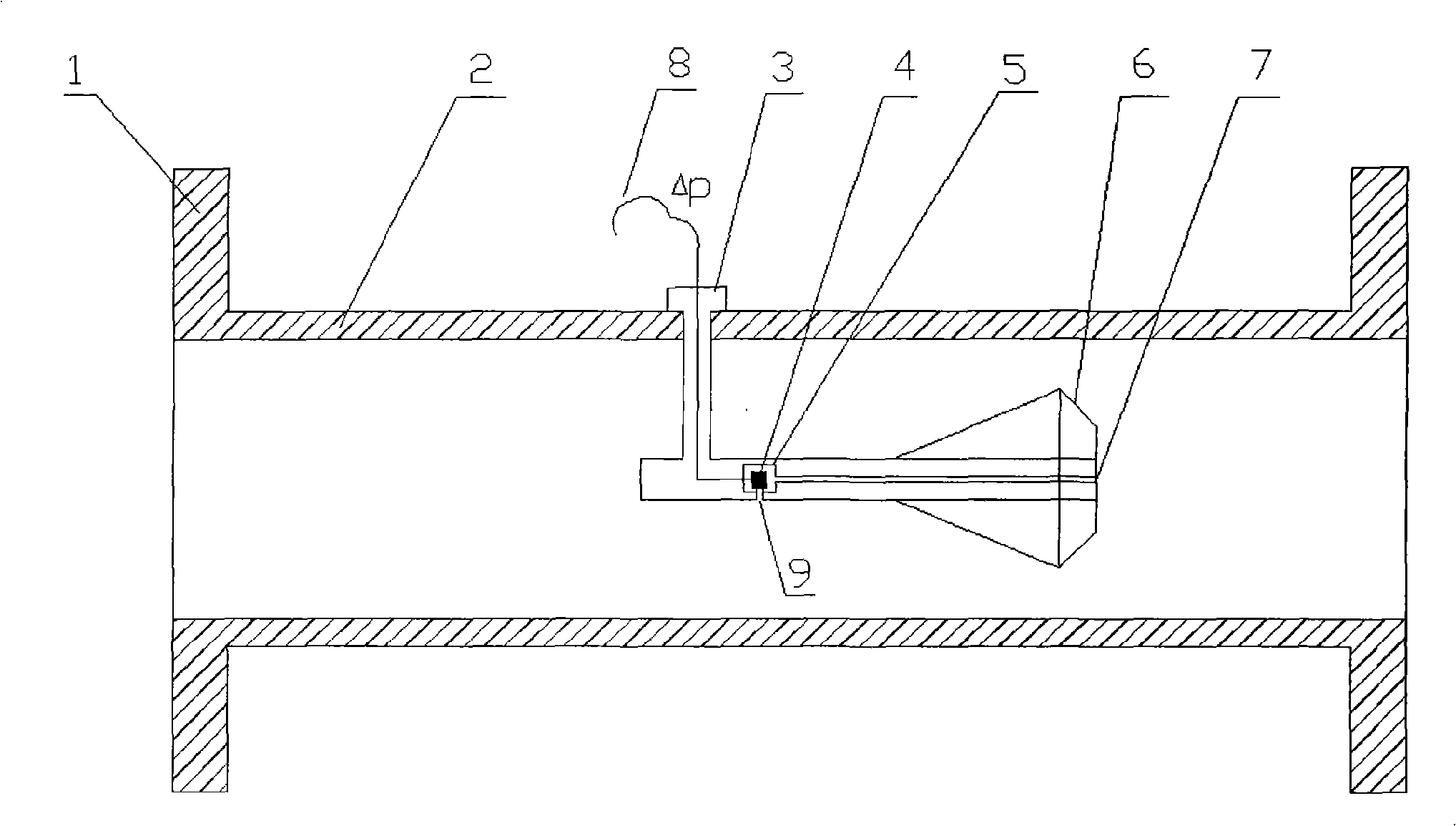
[0024] Such as figure 1 As shown, the front end of the V-shaped cone assembly 6 is fixedly connected to one end of the support frame 3, and the other end of the support frame 3 is fixed on the inner wall of the measuring tube 2; the MEMS sensitive core 4 is packaged in the packaging structure 5 and placed in the V-shaped cone Inside the assembly 6; when the fluid in the measuring tube 2 flows through the V-shaped cone of the V-shaped cone assembly 6, the fluid gradually throttles and shrinks to the inner wall of the pipeline. According to Bernoulli's principle, the V-shaped cone A pressure difference corresponding to the flow rate is generated before and after, and the pressure difference is measured by the MEMS sensitive core 4 and is led out of the measuring tube 2 through the signal line 8 . According to the flow-differential pressure mathematical relationship model and on-site actual calibration, the dynamic and steady-state measurement of flow can be realized.

Embodiment 2

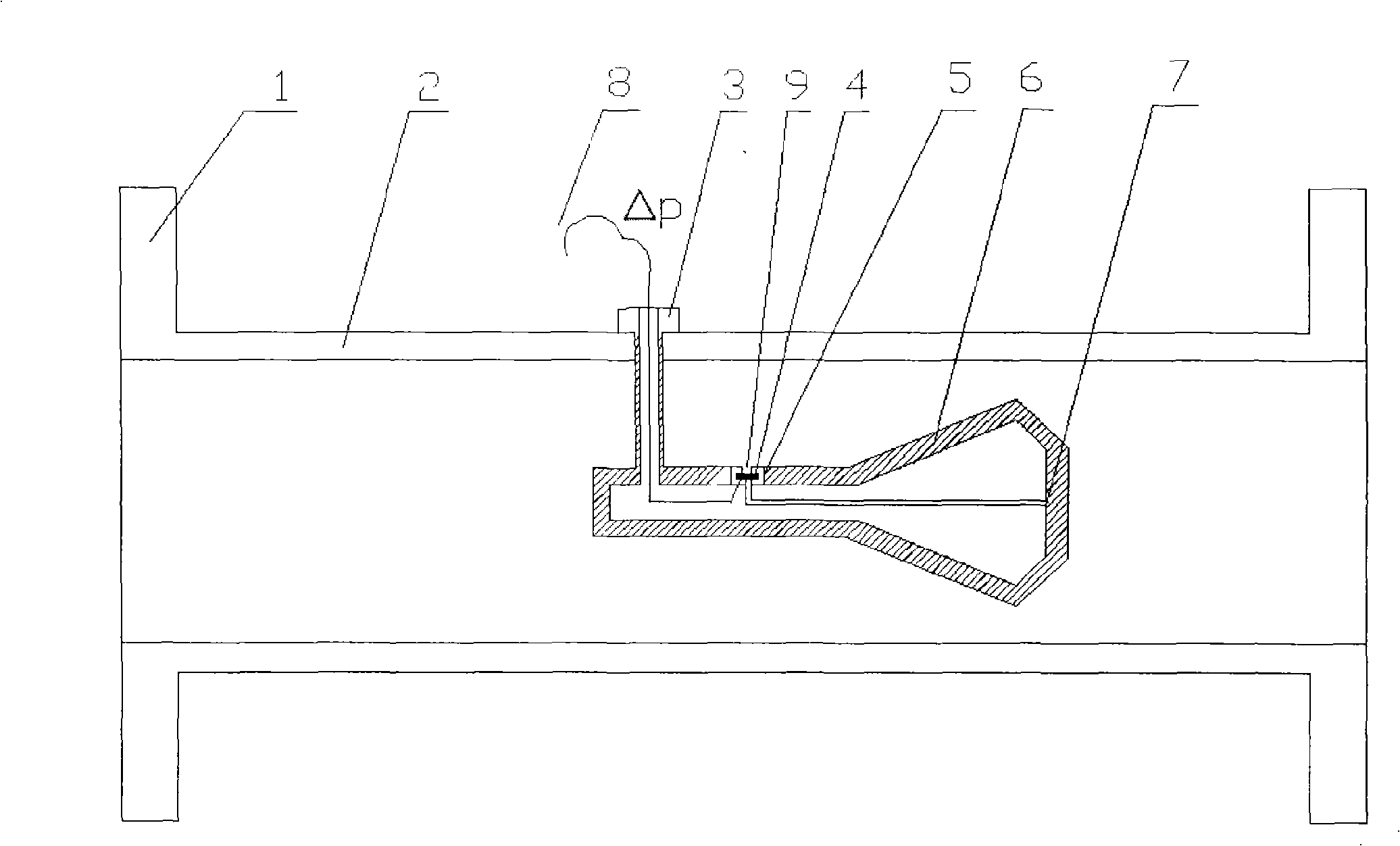
[0026] Such as figure 2 As shown, the front end of the V-shaped cone assembly 6 is fixedly connected to one end of the support frame 3, and the other end of the support frame 3 is fixed on the inner wall of the measuring tube 2; the MEMS sensitive core 4 is packaged in the packaging structure 5 and embedded in the V-shaped cone When the fluid in the measuring tube 2 flows through the V-shaped cone of the V-shaped cone assembly 6, the fluid gradually shrinks to the inner wall of the pipe According to Bernoulli's principle, the V-shaped inner cone produces a pressure difference corresponding to the flow rate, which is measured by the MEMS sensitive core 4 and leads out to the measuring tube 2 through the signal line 8 . According to the flow-differential pressure mathematical relationship model and on-site actual calibration, the dynamic and steady-state measurement of flow can be realized.

Embodiment 3

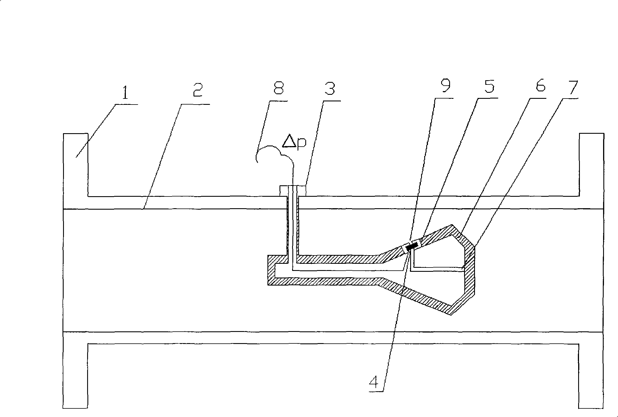
[0028] Such as image 3 As shown, the front end of the V-shaped cone assembly 6 is fixedly connected to one end of the support frame 3, and the other end of the support frame 3 is fixed on the inner wall of the measuring tube 2; the MEMS sensitive core 4 is packaged in the packaging structure 5 and embedded in the V-shaped cone The V-shaped conical tube wall of the assembly 6, and keep sealed with the tube wall; when the fluid in the measuring tube 2 flows through the V-shaped pointed cone of the V-shaped cone assembly 6, the fluid gradually throttles and shrinks into the inside of the pipe As for the side wall, according to Bernoulli's principle, the V-shaped inner cone produces a pressure difference corresponding to the flow rate. The pressure difference is measured by the MEMS sensitive core 4 and leads out to the measuring tube 2 through the signal line 8 . According to the flow-differential pressure mathematical relationship model and on-site actual calibration, the dynam...


PUM


Abstract

The invention relates to a flow measuring device, in particular to a V-cone flow measuring device that is based on an MEMS sensor and consists of a flange, a measuring tube, a supporting frame, an MEMS sensitive core, an encapsulating structure, a positive pressure tapping, a negative pressure tapping, a V-shaped cone component and signal wires. The MEMS sensitive core is arranged inside the V-shaped cone, and the pressure tappings are arranged inside the measuring tube, thus canceling the structure that pressure of traditional V-cone flow meters need to be extracted from the tube. According to a mathematical relation model between the flow rate and the pressure difference as well as real calibration on the spot, the V-cone flow measuring device realizes dynamic and steady-state flow measurement, solves the problems that traditional V-cone flow meters have bad dynamic property, large error and high loss, etc.; furthermore, the invention creates required conditions for the standardization of the V-cone flow meters and is favorable for the popularization and application of the V-cone flow meters.

Description

technical field [0001] The invention relates to a fluid flow measuring device, in particular to a V-cone flow measuring device based on a MEMS sensor for low loss and high response in a circular tube. Background technique [0002] The V-cone flowmeter uses a V-shaped cone coaxially installed in the measuring pipeline to gradually throttle the fluid to the inner wall of the pipeline, and measures the flow rate by measuring the pressure difference between the front and rear of the V-shaped inner cone. Currently, V-cone flowmeters are not standardized. [0003] The traditional V-cone flowmeter consists of a pointed cone mounted coaxially in the measuring tube and two pressure taps on the measuring tube. This type of flowmeter is usually large in size, which brings more energy loss to the pipeline. The differential pressure generating device is separated from the differential pressure transmitting device, and a special pipeline is required to lead the pressure difference out of...

Claims


Application Information

Patent Timeline
Patent Type & Authority Applications(China)
IPC IPC(8): G01F1/34
Inventor 张洪朋安骥左春宽纪玉龙顾长智孙玉清
Owner DALIAN MARITIME UNIVERSITY
Why Eureka
Try Eureka