Denitration and ammonia spraying pipeline flow monitoring device taking reducing agent as urea and application thereof

A technology of flow monitoring and reducing agent, which is applied in the direction of measuring device, volume/mass flow generated by mechanical effects, liquid/fluid solid measurement, etc. It can solve the problem of blockage of pressure pipes, difficult to reach above 200°C, and differential pressure flowmeters In order to avoid problems such as blockage of the pressure induction pipe, the effects of small throttling loss, wide range ratio, and blockage prevention are achieved.

Active Publication Date: 2019-07-09
南京博沃科技发展有限公司
View PDF9 Cites 0 Cited by
  • Summary
  • Abstract
  • Description
  • Claims
  • Application Information

AI Technical Summary

Problems solved by technology

[0006] For differential pressure flowmeters including perforated plate gas flowmeters, the measured primary differential pressure signal must be connected to the differential pressure meter through the pressure introduction tube. It is very difficult for some components of the measured gas to condense and crystallize. It is easy to cause blockage of the pressure induction pipe, which will cause the flowmeter to fail to work normally
For example, the traditional differential pressure flowmeter is used in the occasion where the reducing agent is urea denitrification and ammonia injection pipeline flow monitoring (in the urea pyrolysis or hydrolysis ammonia production process, the medium temperature after mixing with dilution air is generally about 300 ℃), when measuring When the temperature of the medium is lower than 200°C, there will be condensation or even crystallization of urea, which will lead to blockage of the pressure introduction pipe of the differential pressure flowmeter
Although the above-mentioned clogging problem can be alleviated by using heat tracing technology for the pressure induction pipe, it is difficult for the traditional heat tracing technology to reach above 200°C, and it is difficult to guarantee its reliability

Method used


Image

  • Denitration and ammonia spraying pipeline flow monitoring device taking reducing agent as urea and application thereof
  • Denitration and ammonia spraying pipeline flow monitoring device taking reducing agent as urea and application thereof
  • Denitration and ammonia spraying pipeline flow monitoring device taking reducing agent as urea and application thereof

Examples


Embodiment 1

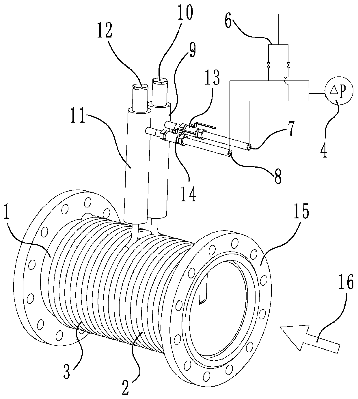
[0030] A denitration ammonia injection pipeline flow monitoring device with urea as the reducing agent, comprising a high-temperature measurement pipeline, an upstream pressure-inducing coil, an upstream connecting pipe, a downstream pressure-inducing coil, a downstream connecting pipe and a differential pressure gauge; the upstream pressure-inducing coil and the downstream The pressure-inducing coils are respectively coiled on the outer wall of the high-temperature measurement pipe, and the number of coils of the upstream pressure-inducing coils and the downstream pressure-inducing coils are both ≥2 turns (for example, 9 turns, 11 turns, or 15 turns, etc.); upstream One end of the pressure-inducing coil is connected to the upstream in the high-temperature measurement pipeline, and the other end is connected to the high-pressure interface of the differential pressure gauge through the upstream nozzle. The nozzle is connected to the low pressure interface of the differential pre...

Embodiment 2

[0034] On the basis of Embodiment 1, the following improvements are further made: in order to improve the sensitivity and accuracy of the measurement, and to improve the adaptability to the uneven flow field, the above-mentioned flow monitoring device also includes a throttle orifice plate, which is installed on the throttle orifice plate. In the high-temperature measurement pipeline, the upstream end of the upstream pressure-inducing coil and the high-temperature measurement pipeline is located upstream of the orifice plate, and the end of the downstream pressure-inducing coil that communicates with the downstream in the high-temperature measurement pipeline is located downstream of the orifice plate. That is, one end of the upstream pressure-inducing coil is connected to the space upstream of the orifice plate in the high-temperature measurement pipeline, the other end is connected to the high-pressure interface of the differential pressure gauge through the upstream nozzle, a...

Embodiment 3

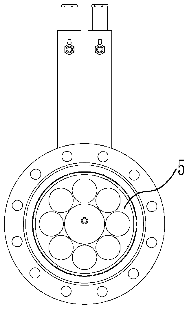
[0036] On the basis of Example 2, the following improvements are further made: In order to improve the adaptability of the flow monitoring device to the uneven flow field, the throttling orifice plate is selected as a porous throttling orifice plate.


PUM


Abstract

The invention discloses a denitration and ammonia spraying pipeline flow monitoring device taking a reducing agent as urea. The device comprises a high temperature measurement pipeline, an upstream pressure coil, an upstream connection pipe, a downstream pressure coil, a downstream connection pipe and a differential pressure gauge, wherein the upstream pressure coil and the downstream pressure coil are respectively coiled on the outer wall of the high temperature measurement pipeline; both the coiling cycles of the upstream pressure coil and the downstream pressure coil are greater than or equal to 2; one end of the upstream pressure coil is communicated with the upstream in the high temperature measurement pipeline; and the other end of the upstream pressure coil is connected with a high-pressure port of the differential pressure gauge through the upstream connection pipe. One end of the downstream pressure coil communicates with the downstream in the high temperature measurement pipeline; and the other end of the downstream pressure coil is connected with a low-pressure port of the differential pressure gauge through the downstream connection pipe. The device is particularly suitable for gas flow measurement of non-uniform flow fields of large-caliber pipelines, has the technical advantages of being high in sensitivity, high in accuracy, wide in range ratio and small in throttling loss and preventing blockage, and is particularly suitable for the occasions with the problem that certain components in gas measurement mediums are condensed and crystalized with cold.

Description

technical field [0001] The invention relates to a flow monitoring device for denitration and ammonia injection pipelines with urea as the reducing agent and its application, and belongs to the technical field of gas flow measurement. Background technique [0002] Gas flow is an important parameter in industrial production process and scientific experiment measurement. Flowmeter is a tool for measuring and testing gas flow. Gas flow measurement is an important part of energy measurement, which plays an important role in ensuring product quality, improving production efficiency, saving energy, and promoting scientific and technological development. [0003] Gas flow measurement is very dependent on application conditions, including gas type, flow conditions, and field application conditions. In the laboratory, the flowmeter can obtain extremely high accuracy, but once the gas conditions or environmental conditions change greatly in the field application, not only the accuracy...

Claims


Application Information

Patent Timeline
Patent Type & Authority Applications(China)
IPC IPC(8): G01F1/34G01F1/42G01F15/12B01D53/79B01D53/78B01D53/56
CPCB01D53/56B01D53/78B01D53/79B01D2251/2067G01F1/34G01F1/42G01F15/12
Inventor 韦红旗石伟伟
Owner 南京博沃科技发展有限公司
Why Eureka
Try Eureka