Vibrating wire sensor installation tool and vibrating wire sensor installation method

A vibrating wire sensor and installation tool technology, which is applied in the measurement, instrument, measuring device and other directions by measuring the frequency change force of the stressed vibration element, can solve the problems of limited accuracy, time-consuming and labor-consuming, time-consuming, etc. Achieve the effect of improving adjustment speed and accuracy, saving time and reducing operational risks

Active Publication Date: 2018-06-15
CENT RES INST OF BUILDING & CONSTR CO LTD MCC GRP
View PDF6 Cites 2 Cited by
  • Summary
  • Abstract
  • Description
  • Claims
  • Application Information

AI Technical Summary

Problems solved by technology

[0015] Moreover, since the manual adjustment of the sensor depends entirely on the experience and feel of the workers, not only does it require repeated adjustments during the adjustment process, which is time-consuming, but also the final adjustment accuracy is limited.
[0016] During the actual testing or monitoring of engineering structures, the surface of the structure to be tested is often located at high altitude or other areas that are difficult for testers to reach, so the operation of installing sensors has some risks (for example, high-altitude operations may be required, etc.)
However, at least the above 6 steps are required to completely perform the above-mentioned process of installing and adjusting the sensor, so it is not only time-consuming and labor-intensive, but also increases the work risk of the installer

Method used


Image

  • Vibrating wire sensor installation tool and vibrating wire sensor installation method
  • Vibrating wire sensor installation tool and vibrating wire sensor installation method
  • Vibrating wire sensor installation tool and vibrating wire sensor installation method

Examples


Embodiment Construction

[0053] In order to make the technical solutions and advantages of the present invention clearer, the present invention will be further described in detail below in conjunction with the accompanying drawings and specific embodiments.

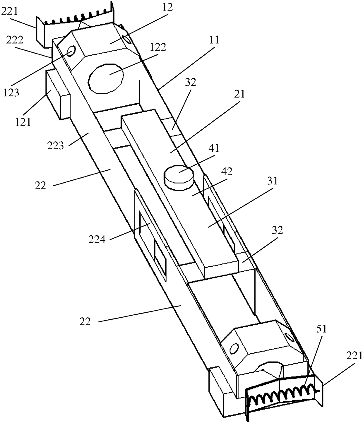
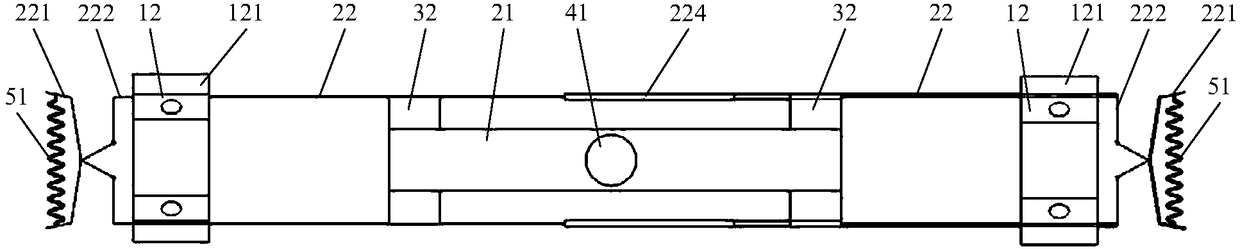
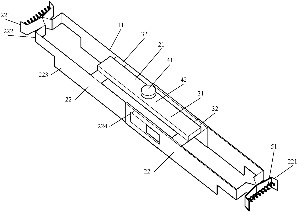
[0054] figure 1 It is a three-dimensional schematic diagram of the installation tool of the vibrating wire sensor in the embodiment of the present invention, figure 2 It is a top view of the installation tool of the vibrating wire sensor in the embodiment of the present invention, image 3 It is a three-dimensional schematic diagram of the installation tool of the vibrating wire sensor after removing the spacer in the embodiment of the present invention, Figure 4 It is a three-dimensional schematic diagram of an installation tool equipped with a vibrating wire sensor in an embodiment of the present invention, Figure 5 It is a schematic diagram of the installation of the vibrating wire sensor and the pad in the embodiment of the present inventi...


PUM

PropertyMeasurementUnit
Lengthaaaaaaaaaa

Abstract

The present invention provides a vibrating wire sensor installation tool and a vibrating wire sensor installation method. The installation tool comprises a cushion block clamp and two cushion blocks;the two sides of the bottom portions of the cushion blocks are respectively provided with protrusion portions, and the middle portions of the cushion blocks are provided with through holes which can be passed through by a vibrating wire sensor; the cushion block clamp comprises a regulation module and two clamps; the middle portions of the two clamps are respectively provided with clamping portions, the top portions of the two clamps are respectively provided with clips, each clamp portion comprises two clamping pieces clamped at two sides of one cushion block, and the tail end of each clamping piece is provided with one connecting piece; the two clamps are slidingly connected through the connecting pieces; the regulation module comprises a regulator and two fixing plates; the two ends ofthe fixing plates are respectively fixed at the two clamping pieces of the clamps; the two ends of the regulator are respectively fixed on the two fixing plates; and the regulator is provided with a fine tuning knob configured to elongate and shorten the length of the regulator. The vibrating wire sensor installation tool and the vibrating wire sensor installation method can save the installationtime of the vibrating wire sensor, can reduce the work risk, and can improve the regulation speed and the precision of the vibrating wire sensor.

Description

technical field [0001] The present application relates to the technical field of stress and strain testing, in particular to an installation tool and an installation method of a vibrating wire sensor. Background technique [0002] Stress-strain testing is a common method for testing engineering structures or structural components during testing, construction, and monitoring, and is an important means to evaluate the safety of structures or components. The location for stress-strain testing can be the surface and interior of structures or components. In the prior art, the main method of stress-strain testing is to measure by installing sensors. The vibrating wire strain sensor has become a commonly used strain test sensor due to its simple structure, reliable operation and good durability. [0003] The vibrating wire strain sensor consists of three components: an outer cylinder, a vibrating wire, and an electromagnetic coil, and is connected to the surface of the structure ...

Claims


Application Information

Patent Timeline
IPC IPC(8): G01L1/00G01L1/10
CPCG01L1/00G01L1/10
Inventor 刘宇飞雷素素郭小华崔政涛关键毕登山
Owner CENT RES INST OF BUILDING & CONSTR CO LTD MCC GRP
Why Eureka
Try Eureka