A tooling for the withstand voltage test of a chip optocoupler

A technology of withstand voltage test and optocoupler, which is applied in the direction of testing dielectric strength and measuring device shell, etc., can solve the problem that test tooling is not suitable for batch testing, etc., achieves the advantages of convenient and safe use, easy installation of optocoupler, and improvement of experimental results Effect

Active Publication Date: 2020-10-30
浙江八达电子仪表有限公司 +1
View PDF7 Cites 0 Cited by
  • Summary
  • Abstract
  • Description
  • Claims
  • Application Information

AI Technical Summary

Problems solved by technology

[0003] Aiming at the deficiencies of the prior art, the present invention discloses a tooling for the SMT optocoupler withstand voltage test, which can solve the problem that the existing testing tooling is not suitable for batch testing

Method used


Image

  • A tooling for the withstand voltage test of a chip optocoupler
  • A tooling for the withstand voltage test of a chip optocoupler
  • A tooling for the withstand voltage test of a chip optocoupler

Examples


Embodiment 1

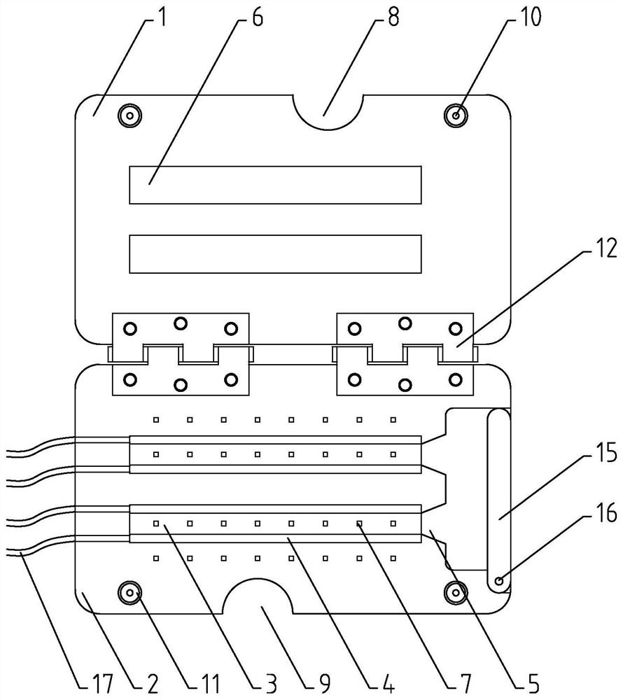
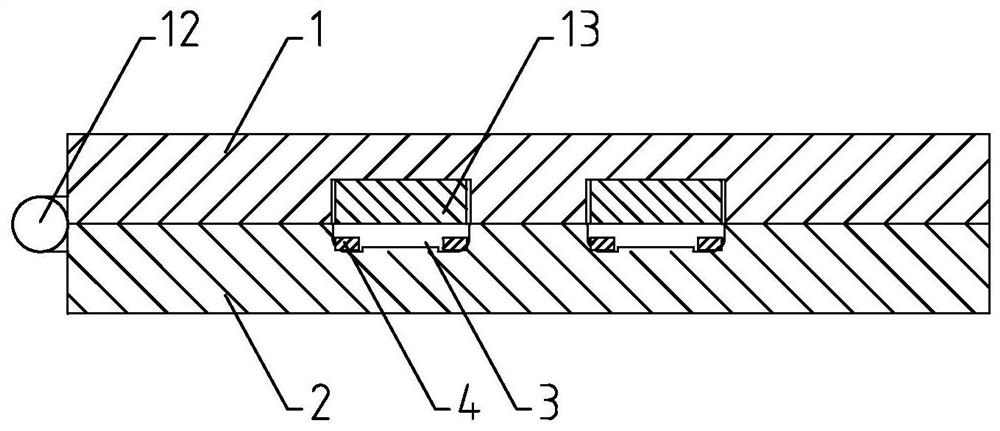
[0021] Such as figure 1 and figure 2 As shown in the embodiment of the present invention, a tooling for SMD optocoupler withstand voltage test includes an upper casing 1 and a lower casing 2. The upper casing 1 and the lower casing 2 are connected by a hinge 12 to facilitate the rotation The upper casing 1 and the lower casing 2 are driven to open or close. Both the upper casing 1 and the lower casing 2 are made of transparent insulating material (such as plastic), which is safe to use without leakage and is convenient for observing the experiment process. The lower housing 2 is provided with a lower test slot 3 for accommodating a plurality of optocouplers. The lower test slot 3 is provided with two parallel conductive slots, and a conductive part 4 for supplying power to the optocoupler is arranged in the conductive slot. The conductive part 4 is embedded In the conductive groove, the conductive part 4 can adopt an integrated conductive contact bar, and is connected to an ...

Embodiment 2

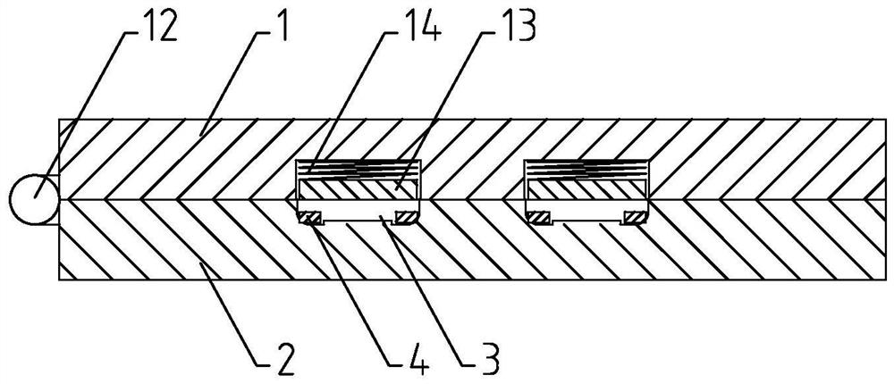
[0029] Such as image 3 As shown, the difference between the embodiment of the present invention and embodiment 1 is that the upper test slot 6 is provided with an elastic member 14 that drives the pressing member 13 to compress the optocoupler. The elastic member 14 can be a compression spring. The pressing part 13 is connected, and the other end of the elastic part 14 is connected with the bottom surface of the upper test groove 6, so as to strengthen the pressure on the optocoupler, thereby improving the experimental effect.

[0030] Refer to Example 1 for other undescribed structures.

[0031] To sum up, the present invention discloses a tooling for withstand voltage test of SMD optocoupler, which adopts transparent and insulated upper shell and lower shell to carry out withstand voltage test for optocoupler, which is convenient and safe to use; Conductive slots are used to install optocouplers in batches, and the transparent upper shell is convenient for observing the ma...


PUM


Abstract

The invention, which relates to the technical field of test fixtures, discloses a tool for testing voltage withstanding of a patch optocoupler. The tool comprises an upper shell and a lower shell thatare in rotation connection. Lower testing slots for accommodating a plurality of optocouplers are formed in the lower shell; two parallel conductive slots are formed in each lower testing slot; conductive members for providing power for the optocouplers are arranged in the conductive slots; and the conductive members are conneted with a voltage withstanding instrument by wires. A guidance inlet for guiding an optocoupler to slide in the slot is arranged at one end of each lower testing slot; a sealing element for sealing the guidance inlet is arranged in each guidance inlet; the sealing elements and the lower shell are in through connection. Compression members for compressing optocouplers in the conducive slots are arranged at the upper shell and are arranged at positions, correspondingto the lower testing slots, of the upper shell. According to the invention, the transparent and insulating upper shell and lower shell are used for carrying out voltage withstanding testing on the optocouplers, so that the operation becomes convenient and safe; and with the sealing elements rotating flexibly, the optocouplers can be installed conveniently and sliding out of the optocouplers can beprevented.

Description

technical field [0001] The invention relates to the technical field of testing tooling, in particular to a tooling for pressure-resistant testing of patch optocouplers. Background technique [0002] Existing optocoupler devices need to undergo factory inspection before use, including various electrical performance tests. The electrical performance tests include withstand voltage tests, current tests, etc., and must meet technical requirements before they can be used. At present, when optocoupler devices are tested for withstand voltage, a single optocoupler is directly electrically connected to the withstand voltage instrument through the test line. The pins of the optocoupler are welded on the pad, and the pad is then electrically connected to the test line. After testing the optocoupler for the first time, it is necessary to separate the optocoupler pins from the pads, which not only consumes time and effort, but also makes the test efficiency low, and the test is inconven...

Claims


Application Information

Patent Timeline
Patent Type & Authority Patents(China)
IPC IPC(8): G01R31/12G01R1/04
CPCG01R1/04G01R31/12
Inventor 张辉虎蒋梦影何丽茜曾淑飞陶敬荣刘先进
Owner 浙江八达电子仪表有限公司
Why Eureka
Try Eureka