Fluid sensing device

A technology of induction device and fluid, applied in the direction of measurement device, sound wave re-radiation, instrument, etc., can solve the problems of magnetic material involving water, impeller blade magnetic material is expensive, requires large space, etc., to solve the certification and cost problems, reducing the difference in judgment, and saving space

Pending Publication Date: 2018-06-15
GUANGZHOU SEAGULL KITCHEN & BATH PROD
View PDF0 Cites 0 Cited by
  • Summary
  • Abstract
  • Description
  • Claims
  • Application Information

AI Technical Summary

Problems solved by technology

[0003] This type of technology has the following disadvantages: the impeller itself has a special and expensive magnetic material, and the magnetic material involves water, and many related certifications are difficult to obtain
In addition, one end of some impeller blades is connected to the magnetic block, and there are many parts, which require a large space
Generally, when the fluid flow rate is small, the impeller will not rotate, or the speed is too slow, the magnetic induction device cannot sense the change of the magnetic field, resulting in a difference in judgment or a wrong judgment

Method used


Image

  • Fluid sensing device
  • Fluid sensing device
  • Fluid sensing device

Examples


Embodiment Construction

[0049] The present invention will be further described in detail below in conjunction with the accompanying drawings, so that those skilled in the art can implement it with reference to the description.

[0050] It should be noted that, in the description of the present invention, the terms "horizontal", "vertical", "upper", "lower", "front", "rear", "left", "right", "vertical", The orientation or positional relationship indicated by "horizontal", "top", "bottom", "inner", "outer", etc. is based on the orientation or positional relationship shown in the drawings, and is only for the convenience of describing the present invention and simplifying the description, and It is not to indicate or imply that the device or element referred to must have a particular orientation, be constructed in a particular orientation, or operate in a particular orientation, and thus should not be construed as limiting the invention.

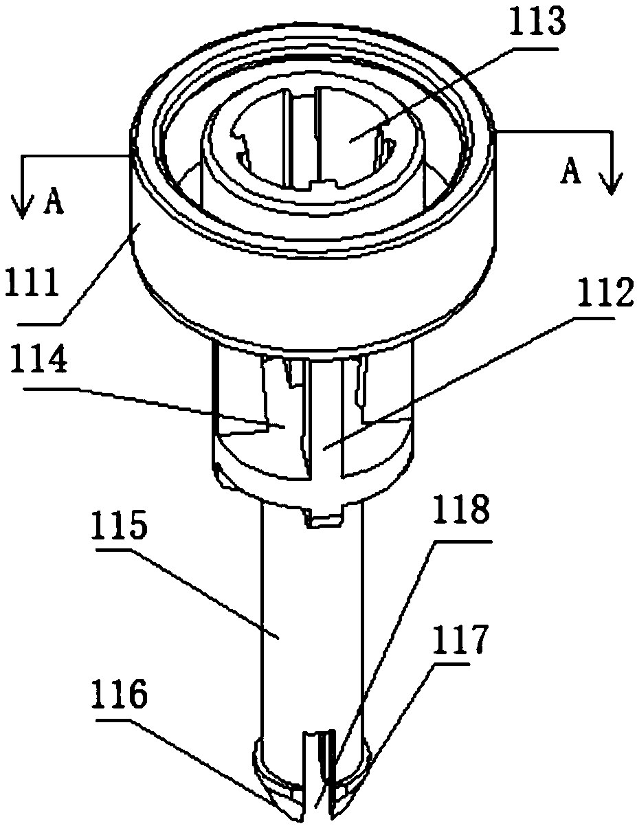
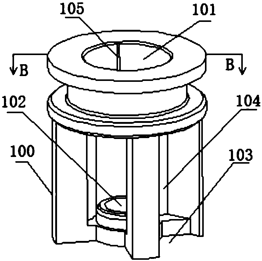
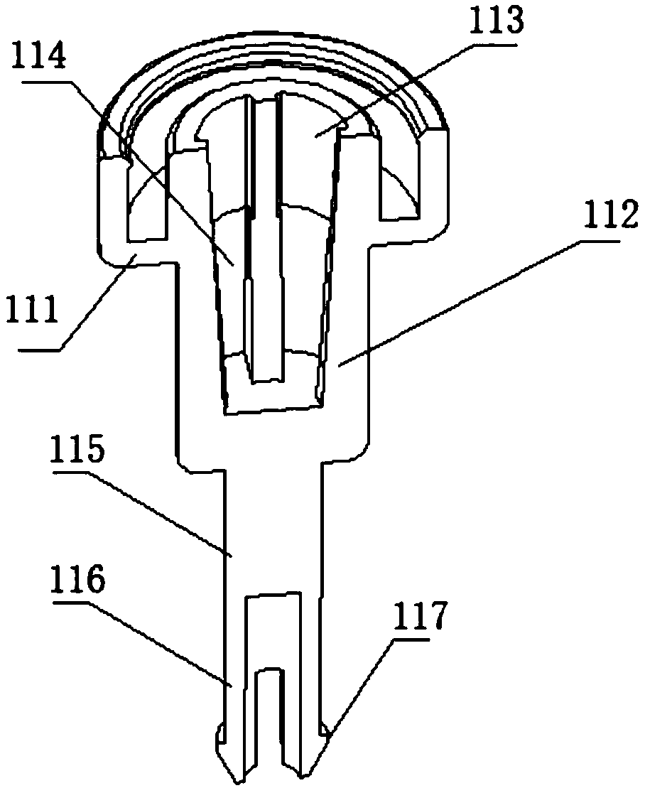
[0051] Such as Figure 1 to Figure 10 As shown, the present inv...


PUM


Abstract

The present invention discloses a fluid sensing device arranged in a flow path through which fluid flows. The device comprises a base fixed in the flow path, a piston core rod disposed in the base andconnected to the same via an elastic component, a magnet disposed on the piston core rod, and a magnetic induction device disposed on a side face of the piston core rod, wherein the piston core rod is provided with a pushing surface which can be pushed via the fluid in the flow path, the magnetic induction device is used to sense magnetic force line change value received as the position of the magnet changes so as to determine whether the fluid flows through the flow path, and the elastic component is disposed in such a way that a direction of restoring force of the elastic component is opposite to a flowing direction of the fluid in the flow path. The fluid sensing device disclosed in the invention is small in quantity of parts and is easy to produce, and difference of determination caused due to small flow rates of the fluid can be reduced.

Description

technical field [0001] The invention relates to an induction device. More specifically, the present invention relates to a fluid sensing device. Background technique [0002] At present, commonly used fluid induction devices generally have impeller blades. When fluid passes through, the fluid flows through the curved blades of the impeller blades, and the fluid will exert force on the impeller blades to make the impeller rotate. Some impellers are magnetic, or some are connected to a magnetic block at one end of the impeller. When the impeller rotates, the magnetic field generated by it also changes. The magnetic induction device senses the change of the magnetic field to determine whether the fluid in the flow path is circulating. state. [0003] This type of technology has the following disadvantages: the impeller blade itself has a special and expensive magnetic material, and the magnetic material involves water, and many related certifications are difficult to obtain. ...

Claims


Application Information

Patent Timeline
Patent Type & Authority Applications(China)
IPC IPC(8): G01V3/08
CPCG01V3/08
Inventor 唐台英
Owner GUANGZHOU SEAGULL KITCHEN & BATH PROD
Why Eureka
Try Eureka