
Fast part identification method based on vision

A recognition method and parts technology, applied to computer parts, character and pattern recognition, instruments, etc., can solve the problems of depth information deviation, difficulty in accurate three-dimensional matching of target areas, missing detection, etc., and achieve the effect of real-time and accurate recognition

Inactive Publication Date: 2018-06-15
广州映博智能科技有限公司
View PDF0 Cites 17 Cited by
  • Summary
  • Abstract
  • Description
  • Claims
  • Application Information

AI Technical Summary

Problems solved by technology

Traditional manual classification cannot be accurately and accurately identified, and there are the following problems: ① slow recognition speed; ② missed detection
[0006] The paper "Target recognition and positioning of binocular stereo vision, Journal of Intelligent Systems, 2011, 6(4): 303-311, Shang Qian, Ruan Qiuqi, Li Xiaoli", uses binocular stereo vision to realize target recognition and positioning; the binocular stereo The vision system mainly includes four modules: camera calibration, image segmentation, stereo matching, and 3D ranging. Stereo matching is the most critical step in binocular vision positioning, but it is difficult to achieve accurate stereo matching in the target area, and stereo matching Inaccuracy will directly lead to deviations in the acquired depth information, and its real-time performance is the biggest challenge faced by binocular and multi-eye positioning vision systems

Method used


Image

  • Fast part identification method based on vision
  • Fast part identification method based on vision
  • Fast part identification method based on vision

Examples


Embodiment Construction

[0019] The present invention will be described in more detail and complete below in conjunction with the accompanying drawings and specific embodiments. It should be understood that the specific embodiments described here are only used to explain the present invention, but not to limit the present invention.

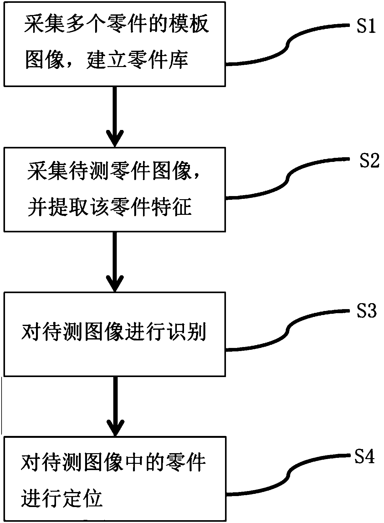
[0020] refer to figure 1 , a vision-based rapid recognition method for parts of the present invention, said method comprising:

[0021] S1, collecting template images of multiple parts, and establishing a parts library;

[0022] Collect template images of multiple parts, each template image represents a type of part, and then extract part features and save them in the part library.

[0023] S2, collecting the image of the part to be tested, and extracting the feature of the part.

[0024] Both steps S1 and S2 must perform image preprocessing operations and image feature extraction operations; where,

[0025] Image preprocessing is an important link in the process of ...


PUM


Abstract

The invention discloses a fast part identification method based on vision. The method comprises steps that S1, template images of multiple parts are acquired, and a part database is established; S2, to-be-detected part images are acquired, and part characteristics are extracted; S3, the to-be-detected images are identified; and S4, the parts of the to-be-detected images are positioned. The methodis advantaged in that through three aspects of the contour number of the parts, geometric characteristics of each contour and shape characteristics of each contour, the to-be-detected part images andtemplate part images of the part database are compared and identified, and the planar parts can be accurately identified, classified and positioned in real time.

Description

technical field [0001] The invention belongs to the field of robot vision positioning, and relates to a vision-based fast identification method for parts. Background technique [0002] Since the 21st century, with the continuous maturity of robot technology, robot technology has been more widely used. From industrial robots to service robots, robots have gradually entered people's daily lives, bringing us a lot of convenience. With the improvement of human material living standards and the increasing enrichment of spiritual life, robots will be more closely linked with human beings in the future. [0003] At present, the industrial robots used in production generally adopt the method of teaching or offline programming, and simply repeatedly execute the pre-programmed programs to complete the actions set by the program, which is subject to many restrictions in industrial production. [0004] In an industrial production line, there will be a large number of parts recognition...

Claims


Application Information

Patent Timeline
IPC IPC(8): G06K9/00G06K9/46
CPCG06V20/10G06V10/44
Inventor 陈墩金覃争鸣杨旭
Owner 广州映博智能科技有限公司
Features
  • Generate Ideas
  • Intellectual Property
  • Life Sciences
  • Materials
  • Tech Scout
  • Unparalleled Data Quality
  • Higher Quality Content
  • 60% Fewer Hallucinations
Learn More