
Self-service photographing device

A technology for equipment and main lighting, which can be applied to coin-operated equipment with instrument control, coin-operated equipment for distributing discrete items, televisions, etc.

Pending Publication Date: 2018-06-15
曾奕
View PDF9 Cites 1 Cited by
  • Summary
  • Abstract
  • Description
  • Claims
  • Application Information

AI Technical Summary

Problems solved by technology

However, when using this lighting solution in a small space, due to the limited installation space of the main lighting source, only a light source with a small light-emitting area can be used, which often causes problems such as local bright spots and uneven lighting; since the light-emitting surface is located on the operation panel The surface or the protruding panel cannot achieve reasonable control of the direction of light, and the light will be reflected multiple times in a small space, often causing defects such as reflections on glasses lenses, background reflections, and lack of three-dimensionality on the faces of characters; because the main lighting is too far away from the characters close, it is prone to defects such as uneven illumination of characters, local bright spots, and heavy background shadows, which cannot achieve satisfactory shooting results

Method used


Image

  • Self-service photographing device
  • Self-service photographing device
  • Self-service photographing device

Examples


Embodiment Construction

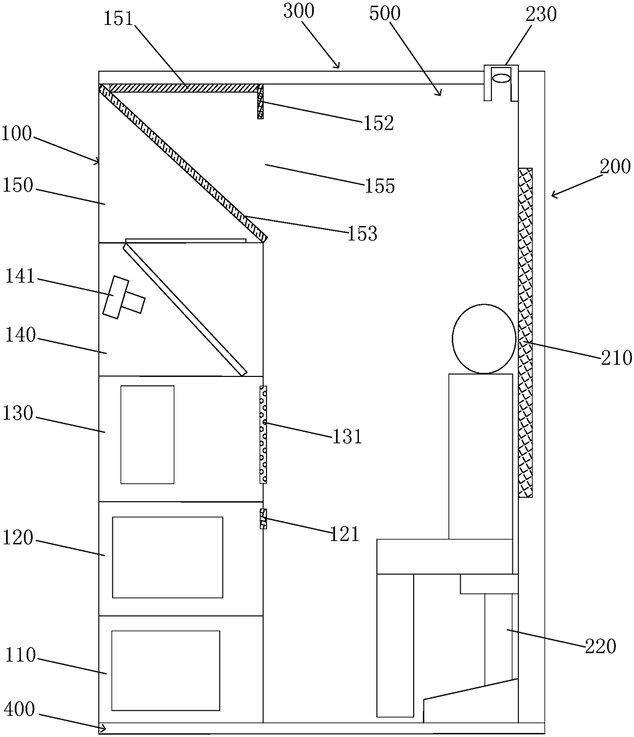
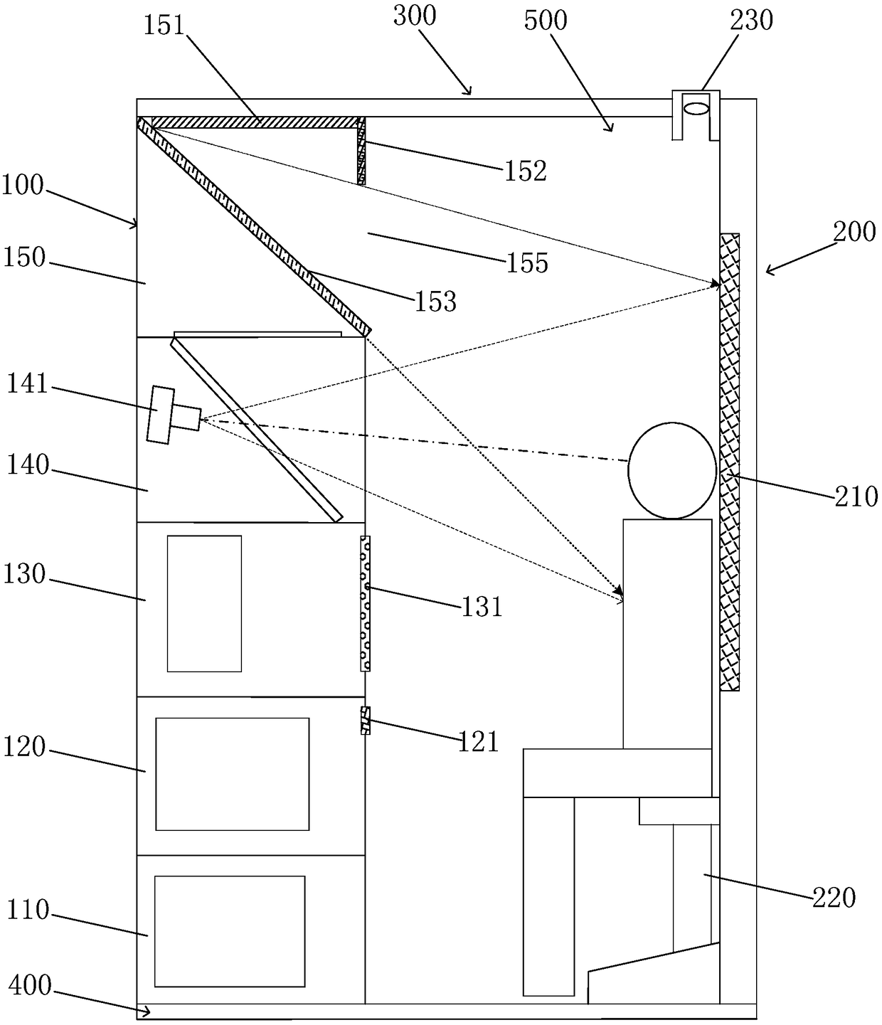
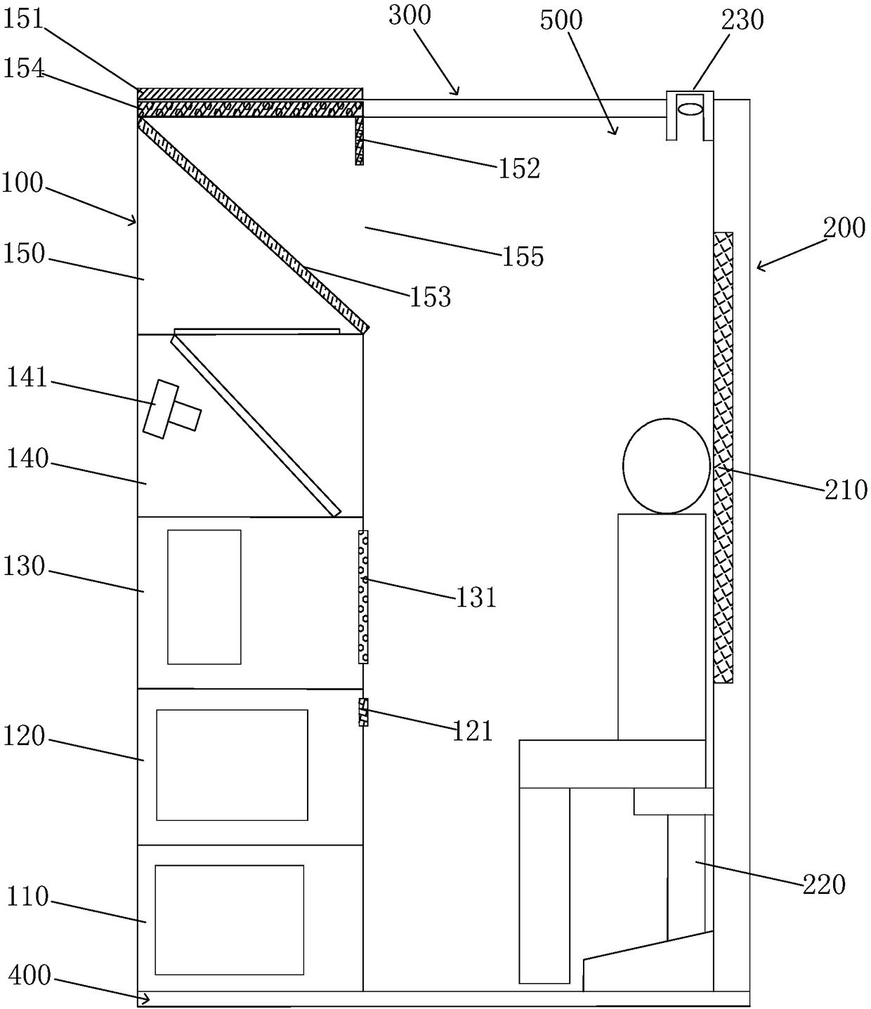
[0038] see below Figure 1 to Figure 5 The self-service photographing equipment of the present invention will be described in detail. In the following description, it should be understood that the terms "upper", "lower", "front", "rear", "left", "right", "vertical", "top" and the like indicate orientation or positional relationship Based on the orientation or positional relationship shown in the drawings, it is only for the convenience of describing the present invention and simplifying the description, and does not indicate or imply that the referred device or element must have a specific orientation, be constructed and operated in a specific orientation, and therefore cannot be construed as a limitation of the invention. where "before" corresponds to Figure 1 to Figure 5 On the left side in , "after" corresponds to Figure 1 to Figure 5 In the right side, "up and down", "vertical" correspond to Figure 1 to Figure 5 in the up and down direction.

[0039] Figure 1 ~ F...


PUM


Abstract

The invention provides a self-service photographing device. A main light installation chamber is formed in a photographing cabinet body, the main light installation chamber is provided with a window close to a background cabinet body, a main illumination lamp module, an upper light barrier plate and a lower light barrier plate. Light rays emitted by the main illumination lamp module are emitted from the interior of the main light installation chamber via the window, the upper light barrier plate is used for limiting the upper limit of an illumination range of the light rays emitted by the mainillumination lamp module to the upper limit of a visual angle of a camera, and the lower light barrier plate is used for limiting the lower limit of the illumination range of the light rays emitted by the main illumination lamp module to the lower limit of the visual angle of the camera. By adopting the scheme, the average distance between the main illumination lamp module and a person is nearlydoubled, and the illumination area is increased by 50% or above, so that the light rays projected on the person are more uniform, defects such as uneven illumination and shadow are avoided, a good lighting effect in a small space is achieved, photography conditions of professional character photography are achieved, and therefore the photography effect is improved.

Description

technical field [0001] The invention relates to a self-service photographing device. Background technique [0002] Due to the compact shape of the self-service camera, the internal camera and operating space is small (about 0.4 square meters), which makes it very difficult to arrange the photo light source reasonably. Existing design schemes of photo light sources, such as the technical schemes disclosed in ZL201611050465.3, ZL201620968507.0 and ZL201621271918.0, all install the main and auxiliary lighting lamps on the surface of the equipment housing, so that the light-emitting surface of the lighting lamps is located on the operation panel. Surface or raised panels to illuminate figures and backgrounds. However, when using this lighting scheme in a small space, due to the limited installation space of the main lighting source, only a light source with a small light-emitting area can be used, which often causes problems such as local bright spots and uneven lighting; since...

Claims


Application Information

Patent Timeline
Patent Type & Authority Applications(China)
IPC IPC(8): G07F17/00G07F17/26G03B15/05G03B15/06H04N5/225
CPCG03B15/05G03B15/06G07F17/00G07F17/266H04N23/00
Inventor 曾奕
Owner 曾奕
Learn More