Dust removal device for textile equipment
A technology for dust removal devices and textile equipment, applied in cleaning methods and utensils, cleaning methods using tools, chemical instruments and methods, etc., which can solve the problems of easy failure of equipment, reduced service life of equipment, and large amounts of lint and dust, etc. question
- Summary
- Abstract
- Description
- Claims
- Application Information
AI Technical Summary
Problems solved by technology
Method used
Image
Examples
Embodiment 1
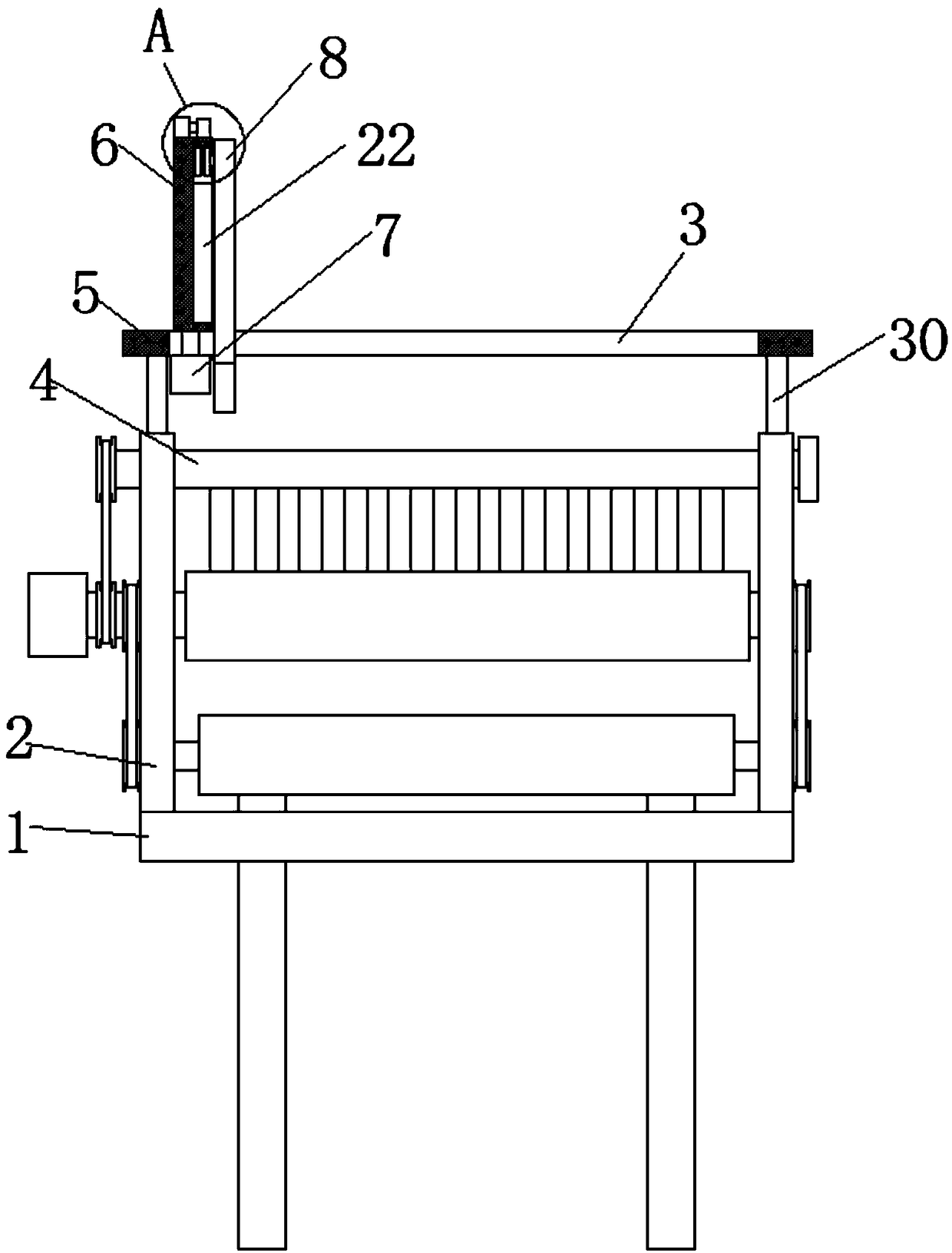
[0027] refer to Figure 1-4 , a kind of dust removal device for textile equipment, comprising an equipment base 1, dust collection boxes are arranged on both sides above the equipment base 1, vertically upward fixing frames 2 are arranged on both sides of the top of the equipment base 1, two fixing brackets 2 The bottom between is provided with the first rotating roller, the middle part between the two fixed mounts 2 is provided with the second rotating roller, and the top between the two fixed mounts 2 is provided with the outlet roller 4, and the tops of the two fixed mounts 2 are Support rods 30 are provided, and a horizontal fixed rod 5 is connected between the two support rods 30. The fixed rod 5 is provided with a horizontal first track groove 3, and a sliding block is installed inside the first track groove 3. The sliding block The top extends to the outside of the first track groove 3 and is connected with a vertically upward drive plate 6, and the bottom of the slidin...
Embodiment 2
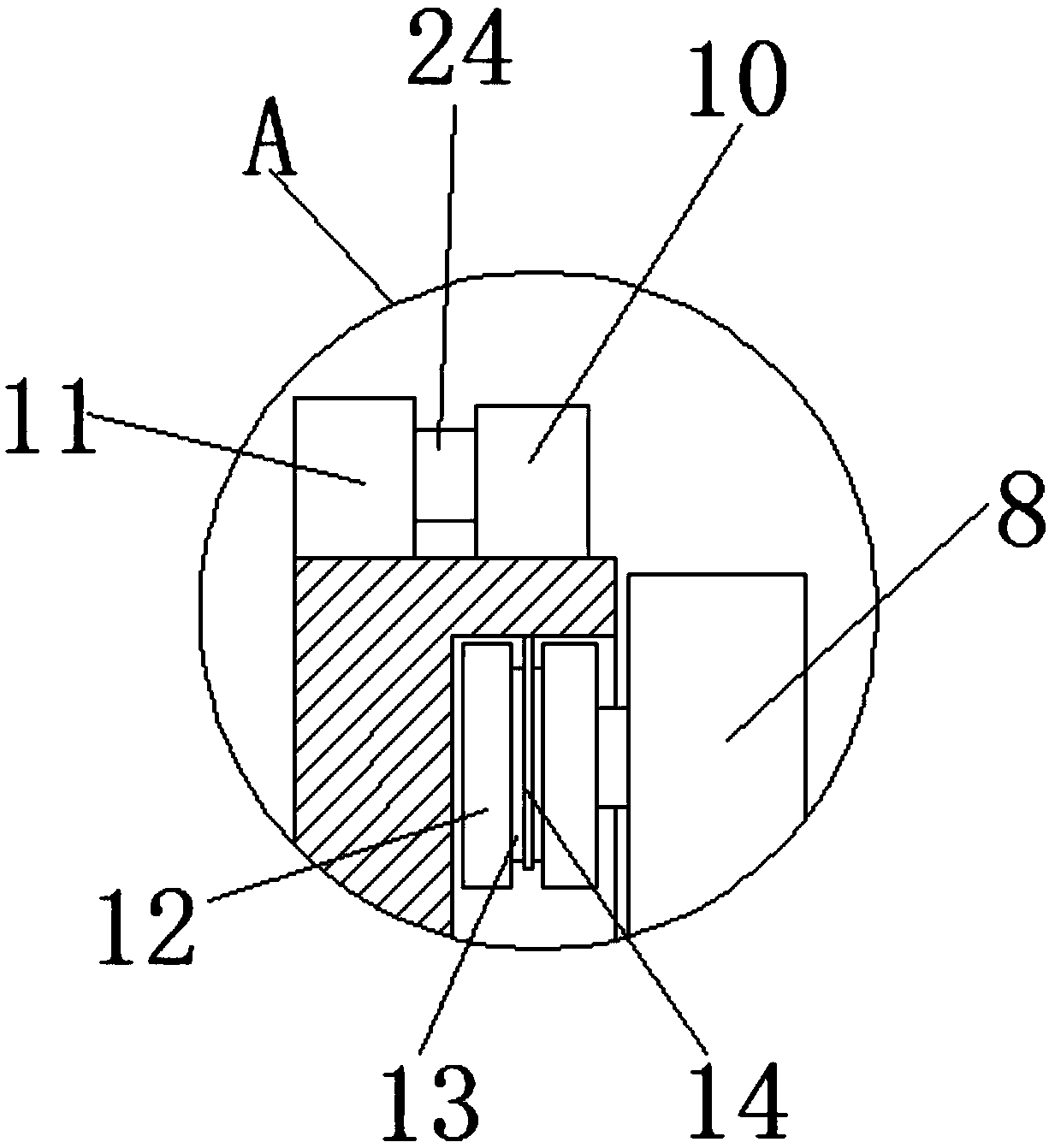
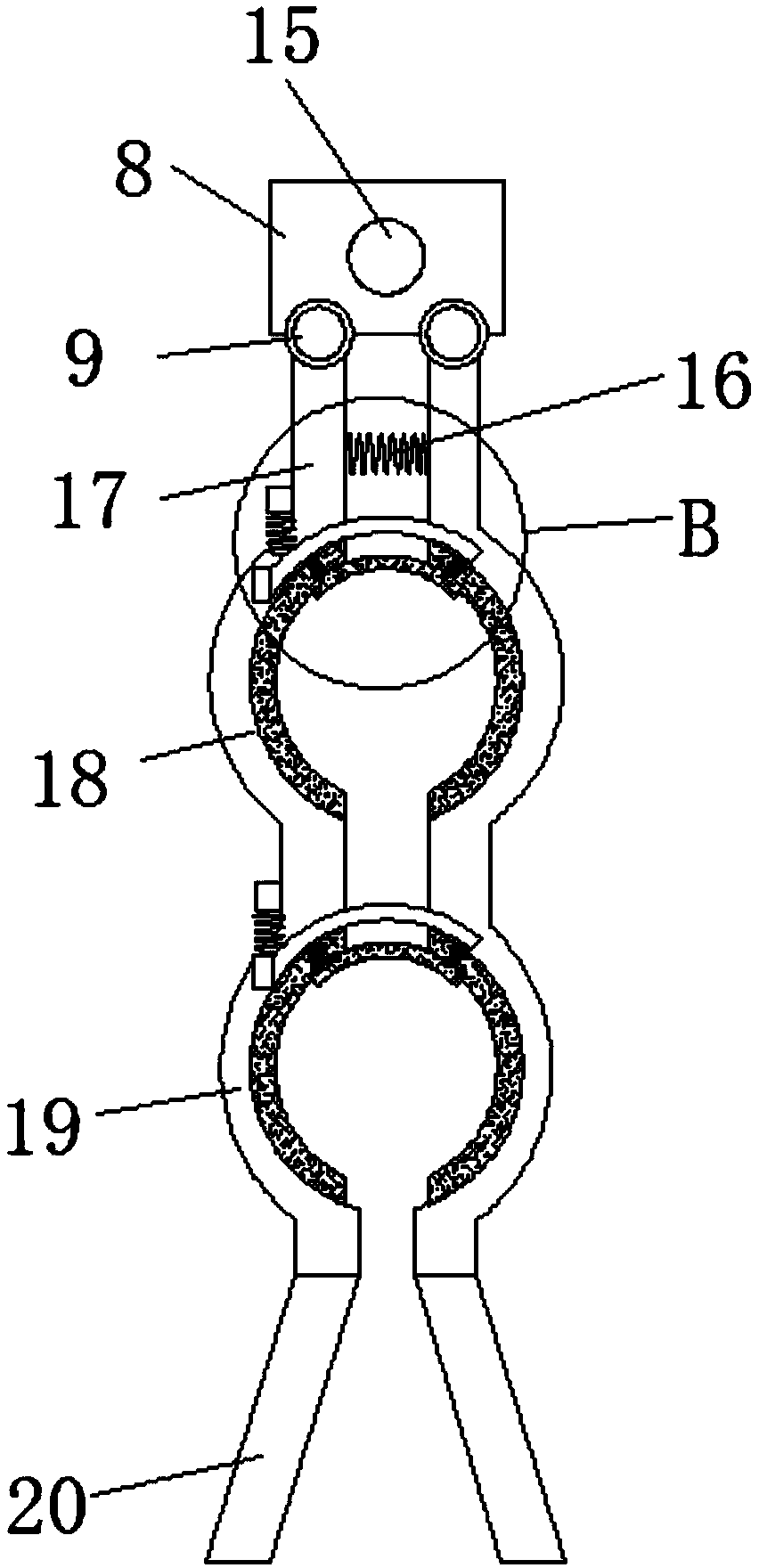
[0029] refer to Figure 2-5 The side of the sliding wheel 12 away from the second track groove 22 is provided with a horizontal connecting rod 15, the other end of the connecting rod 15 is connected with the fixed block 8, and the side where the connecting rod 15 extends to the inside of the fixed block 8 is provided with a rotating block, The fixed block 8 is provided with a mounting groove compatible with the rotating block, the first rotating shaft 9 is provided on both sides of the bottom of the fixed block 8, and the other ends of the two first rotating shafts 9 are provided with a first connecting rod 17 , a horizontal first spring 16 is connected between the two first connecting rods 17, the bottoms of the two first connecting rods 17 are provided with first socket plates 18, and the two first socket plates 18 are close to each other. Both sides are provided with the first cleaning brush, the bottoms of the two first socket plates 18 are all provided with the second conne...
Embodiment 3
[0031] refer to Figure 3-5 , the first connecting rod 17 and the second connecting rod on the bottom side of the fixed block 8 are provided with a connecting block 25, the bottom of the connecting block 25 is connected with a vertical second spring 26, and the first connecting rod on the bottom side of the fixed block 8 Both the socket plate 18 and the second socket plate 19 are provided with a second rotating shaft 27, one side of the second rotating shaft 27 is rotatably connected with a third socket plate 28, two first socket plates 18, two The cross sections of the second socket plate 19 and the two third socket plates 28 are arc-shaped structures, and the top of the third socket plate 28 near the second rotating shaft 27 is fixedly connected with the second spring 26, and the third socket plate 28 is fixedly connected with the second spring 26. The bottom both sides of socket plate 28 are all provided with the 3rd spring 29, and the bottom of two 3rd springs 29 is connec...
PUM
 Abstract
Description
Claims
Application Information
 - R&D
- Intellectual Property
- Life Sciences
- Materials
- Tech Scout
- Unparalleled Data Quality
- Higher Quality Content
- 60% Fewer Hallucinations
Browse by: Latest US Patents, China's latest patents, Technical Efficacy Thesaurus, Application Domain, Technology Topic, Popular Technical Reports.
© 2025 PatSnap. All rights reserved.Legal|Privacy policy|Modern Slavery Act Transparency Statement|Sitemap|About US| Contact US: help@patsnap.com


