A pole displacement and erection device for urban buildings

A technology for utility poles and construction, which is applied in the field of utility pole displacement and erection equipment, and can solve problems such as time-consuming and labor-intensive installation of utility poles, inaccurate and stable positions, etc.

Active Publication Date: 2020-04-07
林向亮
View PDF5 Cites 0 Cited by
  • Summary
  • Abstract
  • Description
  • Claims
  • Application Information

AI Technical Summary

Problems solved by technology

[0006] In order to overcome the disadvantages of time-consuming and labor-intensive manual transportation by workers and the inaccurate and stable installation position of the utility poles during the installation of the utility poles, the technical problem to be solved by the invention is to provide a time-saving utility model that does not require manual transportation by workers. It is a pole displacement and erection device for urban buildings that saves labor and has accurate and stable pole installation positions during installation.

Method used


Image

  • A pole displacement and erection device for urban buildings
  • A pole displacement and erection device for urban buildings
  • A pole displacement and erection device for urban buildings

Examples


Embodiment 1

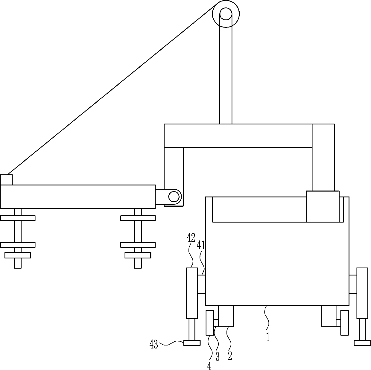
[0037] A pole displacement and erection device for urban buildings, such as Figure 1-8 As shown, it includes a mounting frame 1, a first support seat 2, a wheel shaft 3, a tire 4, a first slide rail 5, a first slider 6, a support plate 7, a fixed plate 8, a connecting rod 9, and an electric reel 10. , the second support seat 11, the first rotating shaft 12, the rotating block 13, the first connecting plate 14, the first screw rod 15, the pressing plate 16, the supporting plate 17, the first nut 19, the first connecting block 20 and the steel wire rope 21, the mounting frame 1 The first support base 2 is installed on the left, right, front and rear sides of the lower side by welding, the outer side of the first support base 2 is rotatably connected to the wheel shaft 3, the wheel shaft 3 is connected to the tire 4, and the upper side of the mounting frame 1 passes through The first sliding rail 5 is installed in the way of bolt connection, and the first sliding block 6 is slid...

Embodiment 2

[0039] A pole displacement and erection device for urban buildings, such as Figure 1-8 As shown, it includes a mounting frame 1, a first support seat 2, a wheel shaft 3, a tire 4, a first slide rail 5, a first slider 6, a support plate 7, a fixed plate 8, a connecting rod 9, and an electric reel 10. , the second support seat 11, the first rotating shaft 12, the rotating block 13, the first connecting plate 14, the first screw rod 15, the pressing plate 16, the supporting plate 17, the first nut 19, the first connecting block 20 and the steel wire rope 21, the mounting frame 1 The first support base 2 is installed on the left, right, front and rear sides of the lower side by welding, the outer side of the first support base 2 is rotatably connected to the wheel shaft 3, the wheel shaft 3 is connected to the tire 4, and the upper side of the mounting frame 1 passes through The first sliding rail 5 is installed in the way of bolt connection, and the first sliding block 6 is slid...

Embodiment 3

[0042] A pole displacement and erection device for urban buildings, such as Figure 1-8As shown, it includes a mounting frame 1, a first support seat 2, a wheel shaft 3, a tire 4, a first slide rail 5, a first slider 6, a support plate 7, a fixed plate 8, a connecting rod 9, and an electric reel 10. , the second support seat 11, the first rotating shaft 12, the rotating block 13, the first connecting plate 14, the first screw rod 15, the pressing plate 16, the supporting plate 17, the first nut 19, the first connecting block 20 and the steel wire rope 21, the mounting frame 1 The first support base 2 is installed on the left, right, front and rear sides of the lower side by welding, the outer side of the first support base 2 is rotatably connected to the wheel shaft 3, the wheel shaft 3 is connected to the tire 4, and the upper side of the mounting frame 1 passes through The first sliding rail 5 is installed in the way of bolt connection, and the first sliding block 6 is slida...


PUM


Abstract

The invention relates to telegraph pole mounting equipment, in particular to telegraph pole displacement and upright equipment for city buildings. According to the telegraph pole displacement and upright equipment for the city buildings, manual transportation by workers is not required, the time and labor are saved, and during mounting, the mounting position of a telegraph pole is precise and stable. The telegraph pole displacement and upright equipment for the city buildings comprises a mounting frame, first supporting seats, a wheel axle, tires, a first sliding rail, a first sliding block and the like; and the first supporting seats are mounted on the left and right sides as well as the front and rear sides of the lower side of the mounting frame in a welded mode. According to the telegraph pole displacement and upright equipment for the city buildings, the effects that manual transportation by the workers is not required, the time and labor are saved, and during mounting, the mounting position of the telegraph pole is precise and stable are achieved; and the telegraph pole can be mounted precisely and stably in a mode that a second air cylinder drives the telegraph pole to movedownwards to enter the mounting position.

Description

technical field [0001] The invention relates to a utility pole installation device, in particular to a utility pole displacement and erection device for urban buildings. Background technique [0002] Telephone poles, as the name implies, are the poles for wires. Appearing in various villages-fields-roads-streets, it was one of the important infrastructures in early China. All kinds of electric poles in the early days started from wooden poles, even including high-voltage electric poles whose voltage level was not too high. Later, due to the development of steel and reinforced concrete, and technical requirements, these two materials replaced most of the wooden poles, and the applicable wood was gradually scarce, and it was basically difficult to see wooden poles in the city. However, in some less developed places, wooden poles are still used to erect telephone lines, because wooden poles are light in weight and easy to erect, and the load-bearing and tensile force of telep...

Claims


Application Information

Patent Timeline
Patent Type & Authority Patents(China)
IPC IPC(8): E04H12/34E04G21/16
CPCE04G21/162E04H12/34
Inventor 高地发蒋安绍
Owner 林向亮
Why Eureka
Try Eureka