computer shock absorber

A computer and shock absorber technology, applied in the direction of supporting machines, springs/shock absorbers, mechanical equipment, etc., can solve the problem of no computer shock absorber, and achieve the effect of avoiding slack and mutual separation

Active Publication Date: 2020-03-06
南京奥利信息技术有限公司
View PDF9 Cites 0 Cited by
  • Summary
  • Abstract
  • Description
  • Claims
  • Application Information

AI Technical Summary

Problems solved by technology

[0004] The problem to be solved by the present invention is that there is no problem that there is no special computer shock absorber at present

Method used


Image

  • computer shock absorber
  • computer shock absorber

Examples


Embodiment Construction

[0012] The present invention will be further described below in conjunction with the accompanying drawings and embodiments.

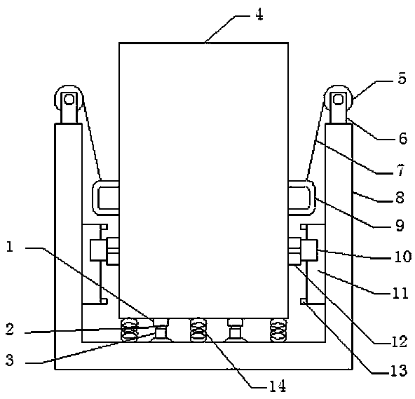
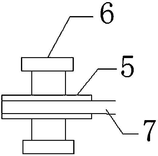
[0013] A computer shock absorber of the present invention comprises a fisheye bearing 1, a pin shaft 2, a suction cup 3, a main computer 4, a flywheel 5, a wheel frame 6, a wide band 7, a chassis 8, a handle 9, a slider 10, and a slide rail 11 , rubber block 12, limit block 13 and spring 14, each handle 9 is installed on the left and right sides of the main computer 4, a plurality of springs 14 are installed on the bottom plate of the main computer 4, the spring 14 is installed on the chassis 8, and the main computer 4 is installed Fisheye bearing 1, the upper end of the pin shaft 2 is installed in the fisheye bearing 1, the lower end of the pin shaft 2 is installed on the suction cup 3, the suction cup 3 is adsorbed on the chassis 8, and two rubber blocks 12 are installed on the left and right sides of the computer. 12 is installed on the slider 10, th...


PUM


Abstract

A computer antivibrator comprises fisheye bearings, pin shafts, suction cups, a computer host, flywheels, wheel frames, cummerbunds, a bottom frame, handles, sliding blocks, sliding rails, rubber blocks and springs. The handles are mounted on the left side and the right side of the computer host correspondingly. The multiple springs are mounted on a bottom plate of the computer host, and the springs are mounted on the bottom frame. The computer antivibrator has the advantage of having the computer antivibration function.

Description

technical field [0001] The invention relates to a computer shock absorber, which belongs to the technical field of computer aided devices. Background technique [0002] Computer is an essential tool for people to work. All walks of life need computers for office work. In office places with strong movement such as ships, it is necessary to carry out shockproof treatment on the computer to make the computer have shockproof performance to avoid shaking in the office place. Make an impact, but there is currently no dedicated computer shock absorber. In order to solve the above-mentioned difficulties, it is necessary to develop a computer anti-vibration device with a computer anti-vibration function. Contents of the invention [0003] The object of the present invention is to provide a computer shock absorber. [0004] The problem to be solved by the present invention is that there is no special computer shock absorber at present. [0005] For realizing the purpose of the pr...

Claims


Application Information

Patent Timeline
Patent Type & Authority Patents(China)
IPC IPC(8): F16M5/00F16F15/02F16F15/04F16F15/08
CPCF16F15/022F16F15/046F16F15/08F16M5/00
Inventor 徐斌
Owner 南京奥利信息技术有限公司
Why Eureka
Try Eureka