
A Lightweight Pneumatic Horizontal Shock Platform with a Horizontal Shock Absorbing Structure

A light-weight and impact table technology, which is applied in the testing of machines/structural components, shock absorbers, impact testing, etc., can solve problems such as inconvenient replacement and secondary development, potential safety hazards, weak shock isolation capabilities, etc., to reduce Destroy and interfere with surrounding equipment, improve the level of impact resistance, and facilitate secondary development

Inactive Publication Date: 2019-10-15
ZHONGBEI UNIV +1
View PDF12 Cites 0 Cited by
  • Summary
  • Abstract
  • Description
  • Claims
  • Application Information

AI Technical Summary

Problems solved by technology

[0003] In the prior art, because the baffles bear the largest impact force, the front and rear baffles of the horizontal impact test equipment have the characteristics of oversized and heavy structure, inconvenient replacement and secondary development, and weak vibration isolation ability in the horizontal direction. The baffles will be The horizontal impact energy is transmitted to the foundation, resulting in high cost of the foundation, and if the foundation is not well done, the foundation is easily cracked and damaged after multiple impacts
Moreover, relying on the foundation for shock absorption will cause ground vibration, especially horizontal vibration, which will interfere with surrounding equipment and cause safety hazards
[0004] However, some installation conditions cannot be fixed with anchor bolts and foundations, so the horizontal impact table can only be placed directly on the ground. After each impact, the vibration to the ground in the horizontal direction is gone, but the horizontal impact table will slide forward after each impact. Move (2 ~ 4cm), bring safety hazards to the surrounding equipment and personnel, and the horizontal impact table must be hoisted back to the original place with a crane for a period of time during the experiment

Method used


Image

  • A Lightweight Pneumatic Horizontal Shock Platform with a Horizontal Shock Absorbing Structure
  • A Lightweight Pneumatic Horizontal Shock Platform with a Horizontal Shock Absorbing Structure
  • A Lightweight Pneumatic Horizontal Shock Platform with a Horizontal Shock Absorbing Structure

Examples


Embodiment Construction

[0024] The following will clearly and completely describe the technical solutions in the embodiments of the present invention with reference to the accompanying drawings in the embodiments of the present invention. Obviously, the described embodiments are only some of the embodiments of the present invention, not all of them. Based on the embodiments of the present invention, all other embodiments obtained by persons of ordinary skill in the art without making creative efforts belong to the protection scope of the present invention.

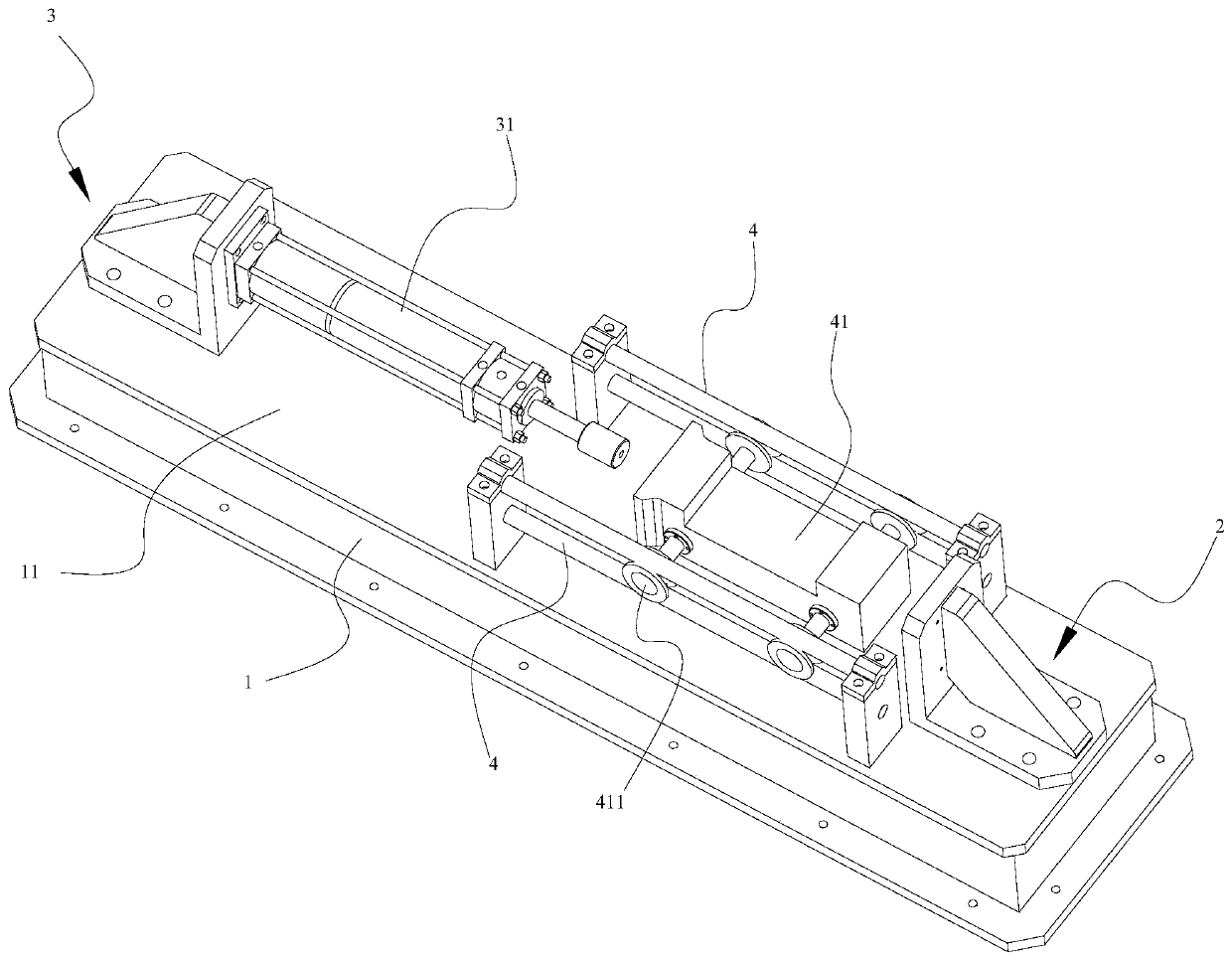
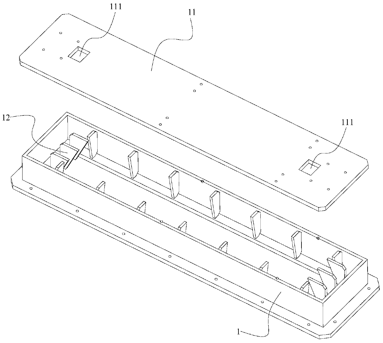
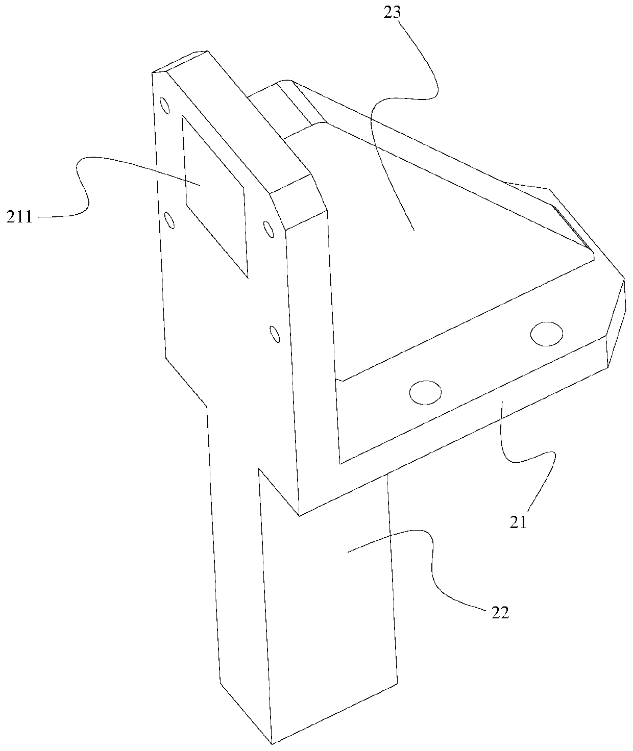
[0025] Such as Figure 1 to Figure 4 As shown, a lightweight pneumatic horizontal impact table with a horizontal shock absorbing structure includes a base 1 with a hollow structure, the base 1 is fixed to the foundation through bolts, and the upper end of the base 1 is fixedly provided with a steel plate 11 capable of covering the base 1 The two ends of the steel plate 11 are symmetrically provided with the first baffle plate 2 and the second baf...


PUM


Abstract

The invention discloses a lightweight pneumatic horizontal impact table with a horizontal shock absorbing structure. The lightweight pneumatic horizontal impact table comprises a base and a steel plate on the base. The steel plate is provided with a first baffle plate, a second baffle plate and a horizontal slide rail. The second baffle plate is provided with a cylinder, and the horizontal slide rail is provided with an energy hammer. The first baffle plate comprises an L-shaped plate, a reinforcing plate and a boss, the L-shaped plate is formed by a vertical plate and a horizontal plate, theenergy hammer strikes the vertical plate and an impact zone is formed, and the steel plate is provided with a notch. The lightweight pneumatic horizontal impact table has the shock absorbing structureand has the advantages of simplified structure, light weight, detachability, easy transportation and easy secondary development and transformation.

Description

technical field [0001] The invention relates to a lightweight pneumatic horizontal shock platform with a horizontal shock absorbing structure. Background technique [0002] The horizontal impact test is a commonly used mechanical environment test. It is used to test the mechanical strength and mechanical shock resistance of electromechanical equipment and structural parts. When it is blocked and stops moving in an instant, the impacted object is subjected to impact and reverse acceleration. In the horizontal impact test, the rear baffle is often used to fix the impacted object, and the front baffle is used to fix the impacted object. Horizontal slip caused by horizontal impact equipment during impact. [0003] In the prior art, because the baffles bear the largest impact force, the front and rear baffles of the horizontal impact test equipment have the characteristics of oversized and heavy structure, inconvenient replacement and secondary development, and weak vibration is...

Claims


Application Information

Patent Timeline
Patent Type & Authority Patents(China)
IPC IPC(8): G01M7/08F16F7/00
Inventor 李波张亚李世中
Owner ZHONGBEI UNIV
Learn More