Power generation screw based on magnetoelectric-piezoelectric composite structure

A composite, piezoelectric technology, applied in the direction of piezoelectric effect/electrostrictive or magnetostrictive motors, screws, generators/motors, etc. problems such as narrow site, to achieve broad application prospects and market application value, reasonable design, simple structure

Inactive Publication Date: 2018-06-19
ZHONGBEI UNIV
View PDF5 Cites 3 Cited by
  • Summary
  • Abstract
  • Description
  • Claims
  • Application Information

AI Technical Summary

Problems solved by technology

[0002] At present, limited by many factors such as space and geological structure, the position and working conditions of the moving parts of coal mining machinery cannot be effectively observed by using the existing lighting system, which is not conducive to ensuring the safety of mine workers
In addition, the coal mining area is a special lighting place, without natural light source for its lighting, the environment is dark and narrow, the surface of the equipment and walls is rough, and the reflection ability of the light source is poor. It poses a great threat to miners' safe operation underground, so it is very necessary to invent a self-powered real-time indicator device for the moving parts of coal mining machinery in the harsh environment of coal mines

Method used


Image

  • Power generation screw based on magnetoelectric-piezoelectric composite structure
  • Power generation screw based on magnetoelectric-piezoelectric composite structure
  • Power generation screw based on magnetoelectric-piezoelectric composite structure

Examples


Embodiment Construction

[0017] Specific embodiments of the present invention will be described in detail below in conjunction with the accompanying drawings.

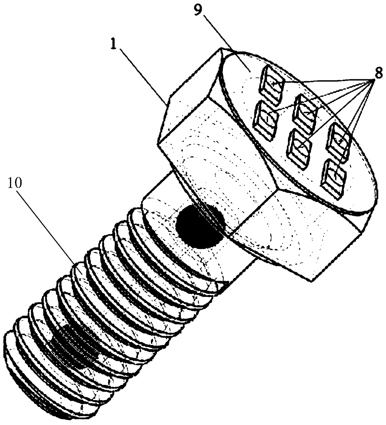
[0018] Such as figure 1 As shown, a power generating screw based on a magnetoelectric-piezoelectric composite structure includes a screw rod 10 and a screw head 1; an LED base 9 is provided on the top surface of the screw head 1, and an LED light strip 8 is provided on the LED base 9.

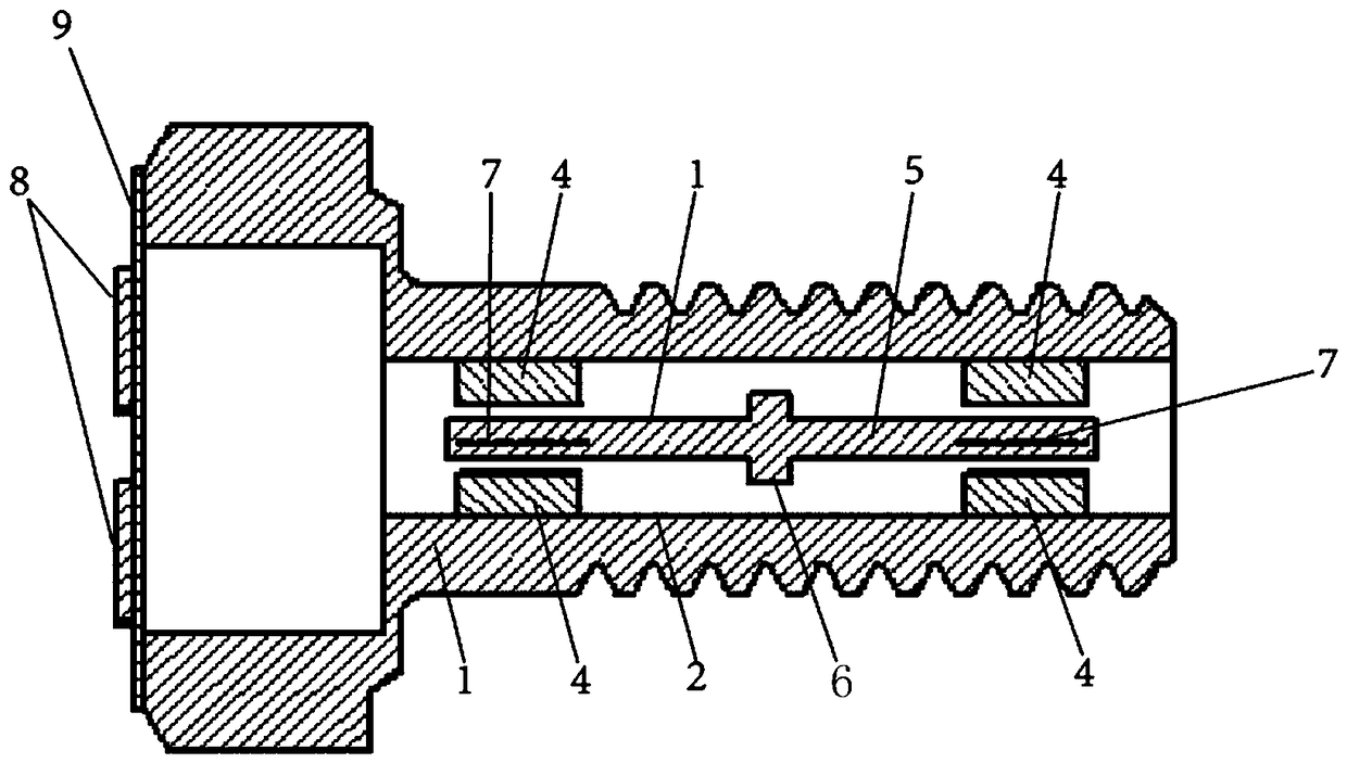
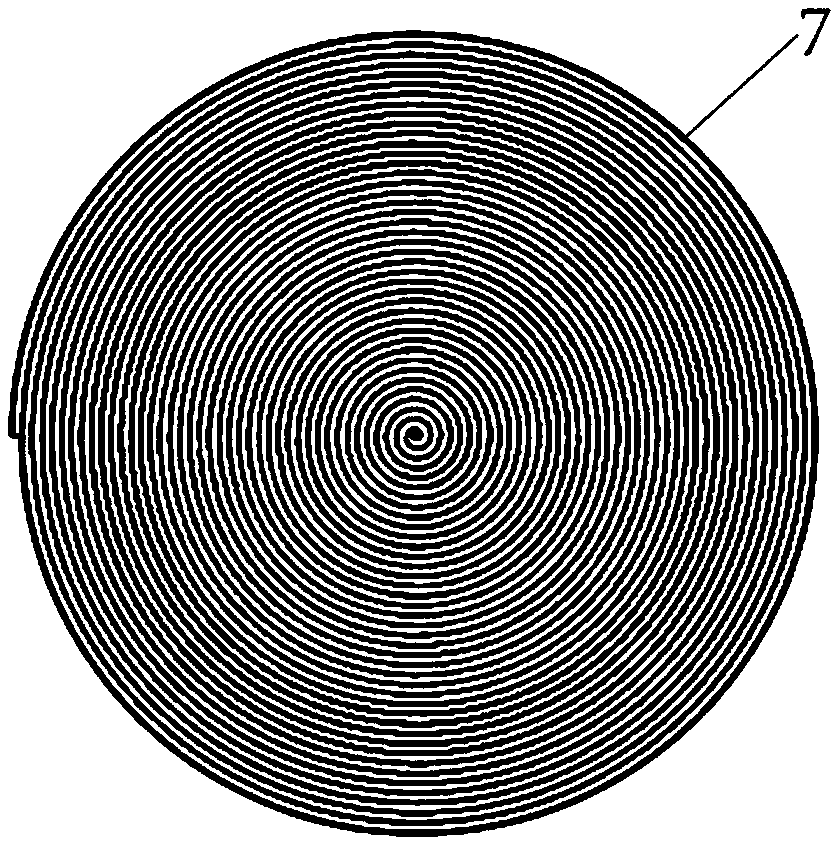
[0019] Such as figure 2 As shown, a hollow cavity is formed in the screw rod 10, a cantilever beam support frame 6 is fixed in the hollow cavity of the screw rod 10, a cantilever beam 5 is installed on the cantilever beam support frame 6, and electromagnetic induction coils 7 are respectively fixed at both ends of the cantilever beam 5 (such as Figure 4 shown), the electromagnetic induction coil 7 (as image 3 As shown), lead wires are connected to the LED base 9; a pair of arc-shaped magnets 4 with opposite polarities are installed in the hollow cavity of ...


PUM


Abstract

The invention discloses a power generation screw based on a magnetoelectric-piezoelectric composite structure. The power generation screw comprises a screw rod and a screw head. The top surface of thescrew head is provided with an LED base which is provided with an LED lamp tape. A hollow cavity is formed in the screw rod. A cantilever beam supporting frame is fixed in the hollow cavity of the screw rod. A cantilever beam is installed on the cantilever beam supporting frame. Electromagnetic induction coils are fixed on the two ends of the cantilever beam. The electromagnetic induction coils are led out of leads to be connected with the LED base. A pair of curved magnets of opposite polarity are installed above and below the electromagnetic induction coils in the hollow cavity of the screwrod. A piezoelectric film is respectively fixed on the upper and lower surfaces of the cantilever beam. The back surface of the piezoelectric film is provided with a layer of electrode which is leadout of the lead to be connected with the LED base. The LED light emitting unit, the magnetoelectric unit and the piezoelectric unit are combined in the screw structure so that the acquired vibration energy can be utilized to be converted into electric energy to light up the LED lamp of the external side of the bolt in case of vibration of the screw.

Description

technical field [0001] The invention belongs to the technical field of micro-energy materials and devices, and in particular relates to the design and processing method of a power generation screw of a magnetoelectric-piezoelectric composite micro-energy collector. Background technique [0002] At present, limited by many factors such as space and geological structure, the position and working conditions of the moving parts of coal mining machinery cannot be effectively observed by using the existing lighting system, which is not conducive to ensuring the safety of mine workers. In addition, the coal mining area is a special lighting place, without natural light source for its lighting, the environment is dark and narrow, the surface of the equipment and walls is rough, and the reflection ability of the light source is poor. It poses a great threat to miners' safe operation underground, so it is very necessary to invent a self-powered real-time indicator device for the movin...

Claims


Application Information

Patent Timeline
Patent Type & Authority Applications(China)
IPC IPC(8): H02N2/18H02K35/04F16B35/00F21V33/00F21Y115/10
CPCF16B35/00F21V33/00F21Y2115/10H02K35/04H02N2/186
Inventor 薛晨阳穆继亮何剑陈曦温涛田竹梅翟聪
Owner ZHONGBEI UNIV
Why Eureka
Try Eureka