Translational flapping wing real-time controllable in direction and pitching and automatic in inclination angle change

A technology of real-time control and variable inclination, which is applied in the fields of translational flapping wings and flying parts, can solve the problems of being easily blown over by the wind, and the swinging flapping wings have no resistance to lateral wind, etc., achieving low manufacturing and use costs, simple structure, The effect of low energy consumption

Inactive Publication Date: 2018-06-22
陆昌新
View PDF6 Cites 20 Cited by
  • Summary
  • Abstract
  • Description
  • Claims
  • Application Information

AI Technical Summary

Problems solved by technology

[0002] Insects and birds achieve flight by swinging their wings on both sides. The wings constantly change angles during flapping. The aircraft wings that imitate this type of flight are called swinging flapping wings. Swinging flapping wings do not have the ability to resist sideways wind. blown over by the wind

Method used


Image

  • Translational flapping wing real-time controllable in direction and pitching and automatic in inclination angle change
  • Translational flapping wing real-time controllable in direction and pitching and automatic in inclination angle change
  • Translational flapping wing real-time controllable in direction and pitching and automatic in inclination angle change

Examples


Embodiment Construction

[0020] The present invention will be further described below in conjunction with the accompanying drawings.

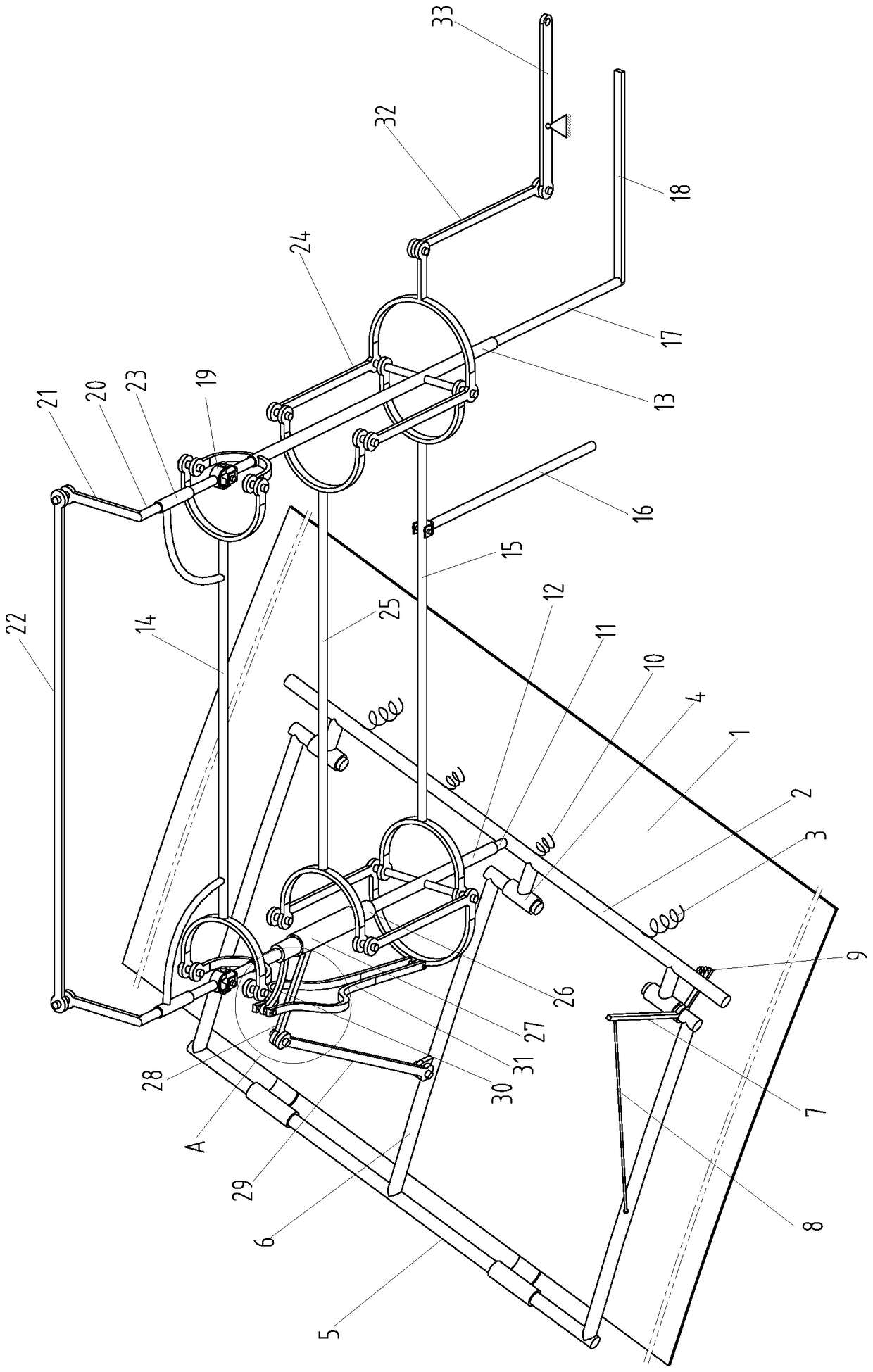
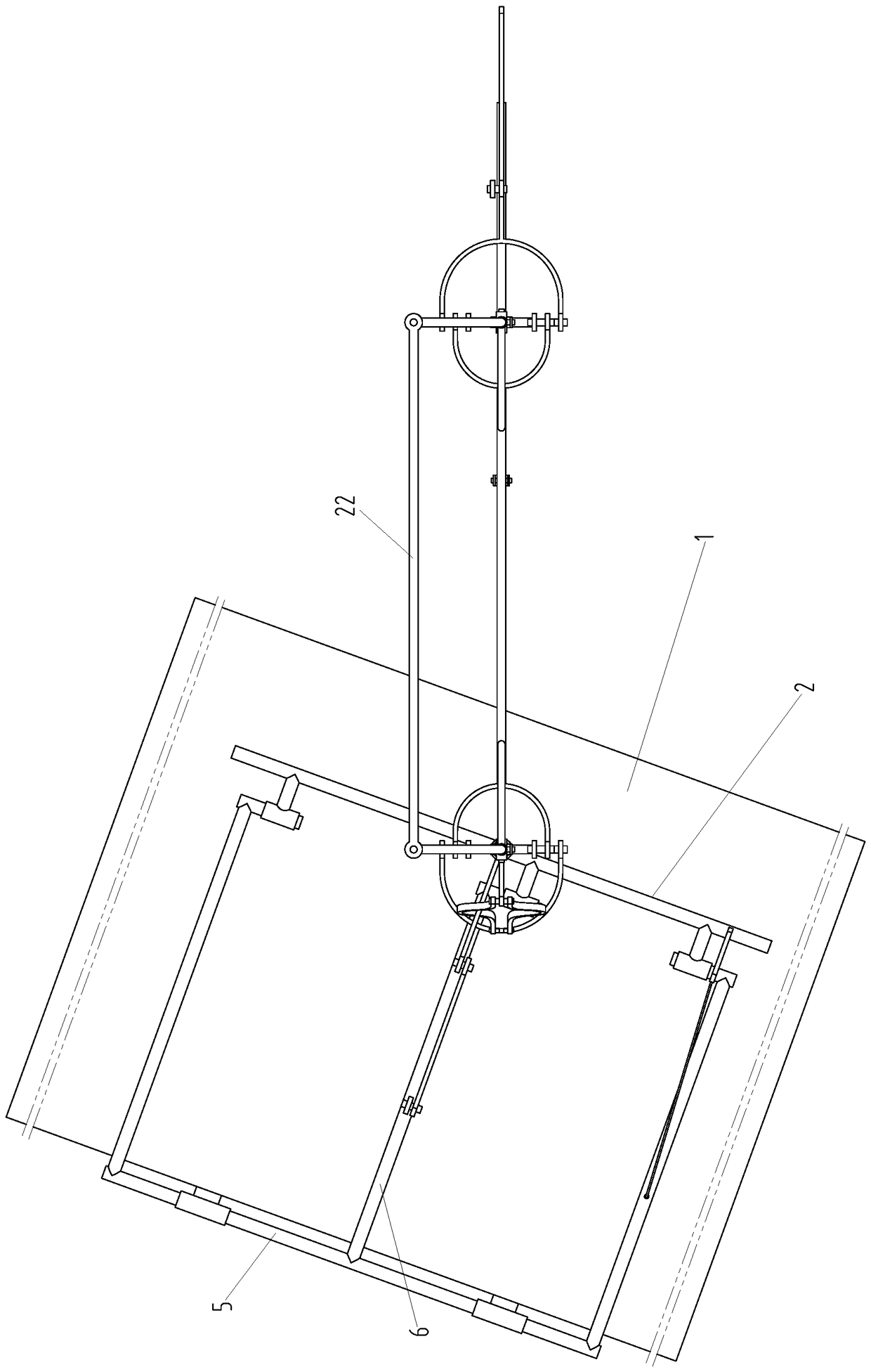
[0021] Such as Figure 1-4 As shown, the wing 1 of the translational flapping wing that can control the direction, pitch and self-inclination angle in real time is placed horizontally. Flapping wing beams 2 arranged parallel to the stretching direction of sheet 1, a tension spring 3 is provided between the flapping wing beams 2 and the top surface of the wings 1 for connection, and a downwardly extending thrust spring 10 is also fixedly connected to the bottom of the flapping wing beams 2, The lower end of the thrust spring 10 is an open end; the flapping wing beam 2 is connected with a plurality of sleeve supports 4, and the front of the flapping wing beam 2 is provided with a variable inclination shaft 5, which is arranged in parallel with the flapping wing beam 2, and There are several variable-inclination beams 6 connected between the inclination shaft 5 and the f...


PUM


Abstract

The invention provides a translational flapping wing real-time controllable in direction and pitching and automatic in inclination angle change. The translational flapping wing adopts a parallelogramdriving mechanism to drive a wing panel, so that the wing panel can always be horizontal when fluttering; furthermore, a steering control mechanism and a pitching control mechanism are arranged for respectively controlling the deflection angle and pitch angle of the wing panel during operation, so that the flapping wing has an ability to resist lateral wind and is flexible to operate. The wing panel of the flapping flap is controlled by a rotating frame consisting of a variable inclination angle shaft and variable inclination angle beams, and a flapping wing beam together; when flapping downwards, the wing panel is subjected to the pressure of the flapping wing beam; when resetting upwards, the wing panel rotates around the variable inclination angle shaft and leaves the flapping wing so as to be not subjected to the force; therefore, the wing panel can automatically change the inclination angle when fluttering up and down, and the flight efficiency is higher. The translational flapping wing is low in energy consumption, high in flight efficiency, simple and firm in structure, low in manufacturing and use costs and good in flexibility and mobility, and is widely used in the fieldssuch as transportation, military, disaster relief, tourism and entertainment.

Description

technical field [0001] The invention relates to a flight component, in particular to a translational flapping wing capable of real-time control of direction, pitch and self-variable inclination, belonging to the technical field of flight equipment. Background technique [0002] Insects and birds achieve flight by swinging their wings on both sides. The wings constantly change angles during flapping. The aircraft wings that imitate this type of flight are called swinging flapping wings. Swinging flapping wings do not have the ability to resist sideways wind. Blown over by the wind. If the wings can always remain horizontal when flapping, it is called a translational flapping wing. The translational flapping wing has the ability to resist lateral wind, and as the wing of the aircraft, it is especially suitable for flying in a narrow space. [0003] In order to realize that the wings of the translational flapping wing can always keep level when fluttering, we have used the pr...

Claims


Application Information

Patent Timeline
Patent Type & Authority Applications(China)
IPC IPC(8): B64C33/02
CPCB64C33/02
Inventor 陆昌新
Owner 陆昌新
Why Eureka
Try Eureka