Spraying type strip steel continuous hot galvanizing system

A technology of hot-dip galvanizing and strip steel, which is applied in the direction of fusion spraying, coating, metal material coating process, etc., and can solve the problems that the surface roughness of the strip steel has a great influence on the quality, the principle process has not changed, scratches, etc. , to achieve the effect of reducing the surface scratch rate and the scrap rate of coiled strip steel, avoiding principle defects, and saving production costs

Active Publication Date: 2018-06-22
新野县天大金具加工有限责任公司
View PDF4 Cites 0 Cited by
  • Summary
  • Abstract
  • Description
  • Claims
  • Application Information

AI Technical Summary

Problems solved by technology

[0002] Hot-dip galvanized sheet is a large amount of sheet and strip products. Traditional hot-dip galvanized products are mainly carried out by using zinc pots, in which sinking rolls are set in the zinc pots, and the strip steel is immersed in the zinc pot by using the sinking rolls and removed from the zinc pot. In this way, the surface of the strip steel can be galvanized, but this traditional method needs to regularly clean the zinc pot, requires the production line to be shut down, and then consumes a lot of manpower and material resources for cleaning, and the zinc The zinc slag generated in the pot is very easy to adsorb on the surface of the strip and scratch the surface of the strip; in addition, the sinking roll set in the zinc pot in the traditional production process is a

Method used


Image

  • Spraying type strip steel continuous hot galvanizing system
  • Spraying type strip steel continuous hot galvanizing system
  • Spraying type strip steel continuous hot galvanizing system

Examples


Embodiment Construction

[0019] The present invention will be further described below in conjunction with specific embodiments. The exemplary embodiments and descriptions of the present invention are used to explain the present invention, but not as a limitation to the present invention.

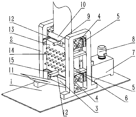
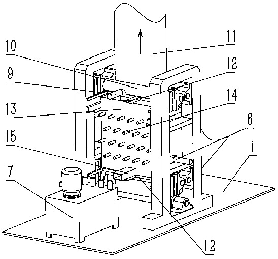
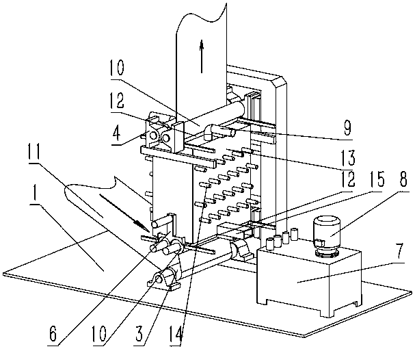
[0020] Such as Figure 1 to Figure 9 A spraying-type continuous hot-dip galvanizing system for strip steel shown includes two supports 2, which are symmetrically installed on the base surface 1, and two conveying rollers 10 are respectively arranged on the upper and lower parts of the two supports 2, The bottom of the two conveying rollers 10 of the bottom is also provided with a turning roller 3, and an insulating cover 13 is arranged between the conveying roller 10 of the upper part and the conveying roller 10 of the lower part. The upper part of the insulating cover 13 is provided with a horizontal slit, and the lower part is provided with an opening. And both sides of the bottom are provided with excess zinc out...


PUM


Abstract

The invention discloses a spraying type strip steel continuous hot galvanizing system. Strip steel is rolled in from a steering roller, enters a heat preservation cover from two conveying rollers at the lower portions of two supports, penetrates the part between spray guns on the two sides of the heat preservation cover from bottom to top, then penetrates out of the heat preservation cover throughan upper horizontal narrow gap of the heat preservation cover and the center position of a pair of air knives located at the upper portion, and is finally conveyed out through two conveying rollers at the upper portions of the two supports. According to the spraying type strip steel continuous hot galvanizing system, creative innovation is conducted on a traditional hot galvanizing system from the principle, a traditional sinking roller is eliminated, galvanizing is conducted in a non-sinking-roller manner, and principle defects of the traditional hot galvanizing manner can be effectively avoided. Through circular supply of zinc liquid of hot galvanizing, the purpose of no zinc slag of a zinc pot is achieved, manpower consumption is effectively reduced, the production cost is saved, and meanwhile the production efficiency is improved. By adoption of the hot galvanizing system, the strip steel surface quality can be effectively guaranteed, the surface scratching rate and the rolled strip steel rejection rate can be obviously reduced, and the yield is improved.

Description

technical field [0001] The invention relates to a hot-dip galvanizing system, in particular to a spray-coating continuous hot-dip galvanizing system for strip steel, which belongs to the technical field of metallurgical equipment. Background technique [0002] Hot-dip galvanized sheet is a large amount of sheet and strip products. Traditional hot-dip galvanized products are mainly carried out by using a zinc pot, in which a sinking roller is set in the zinc pot, and the strip steel is dipped into the zinc pot by the sinking roll and removed from the zinc pot. In order to achieve the purpose of galvanizing the surface of the strip steel, this traditional method requires regular cleaning of the zinc pot and the shutdown of the production line, which consumes a lot of manpower and material resources. The zinc slag generated in the pot is very easy to adsorb on the surface of the strip and scratch the surface of the strip; in addition, the sinking roll set in the zinc pot in the...

Claims


Application Information

Patent Timeline
IPC IPC(8): C23C4/123C23C4/14C23C4/08
Inventor 不公告发明人
Owner 新野县天大金具加工有限责任公司
Why Eureka
Try Eureka