Sliding window anti-falling device easy to install

A technology of anti-falling and anti-falling boards, which is applied to the arrangement of wing leaves, door/window accessories, wing leaf parts, etc., can solve the problems of difficult installation, large frame and door body, and inconvenient operation for installers. Achieve the effects of reducing work difficulty, simple and convenient installation, and avoiding accidental detachment

Active Publication Date: 2018-06-22
佛山市顺德区勒流镇汇强金属制品有限公司
View PDF10 Cites 2 Cited by
  • Summary
  • Abstract
  • Description
  • Claims
  • Application Information

AI Technical Summary

Problems solved by technology

The problem is that after the upper mounting plate and the lower mounting plate are fixed by the first fastener, the lower mounting plate cannot move relative to the upper mounting plate. Insert the part into the installation rail, then slide the installation seat to the corresponding position, and finally fix the anti-fall device of the sliding window and the installation rail. This installation method is difficult to install, and the frame and door are large in size. It is not convenient for the installation personnel to operate, and there are certain limitations

Method used


Image

  • Sliding window anti-falling device easy to install
  • Sliding window anti-falling device easy to install
  • Sliding window anti-falling device easy to install

Examples


no. 1 example

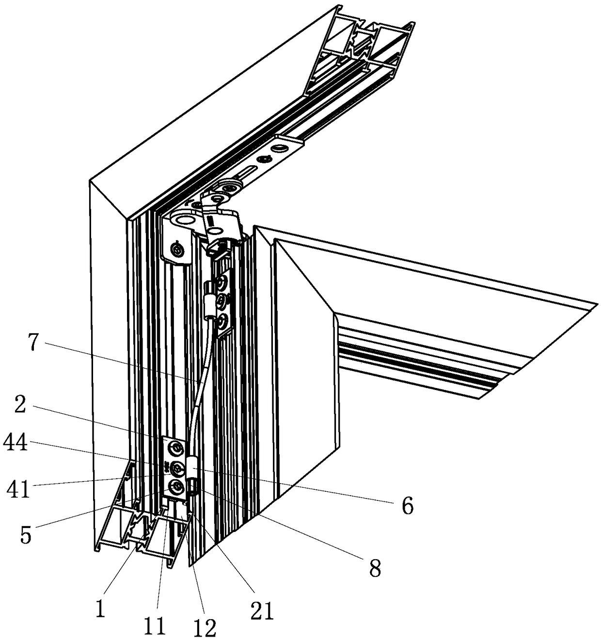
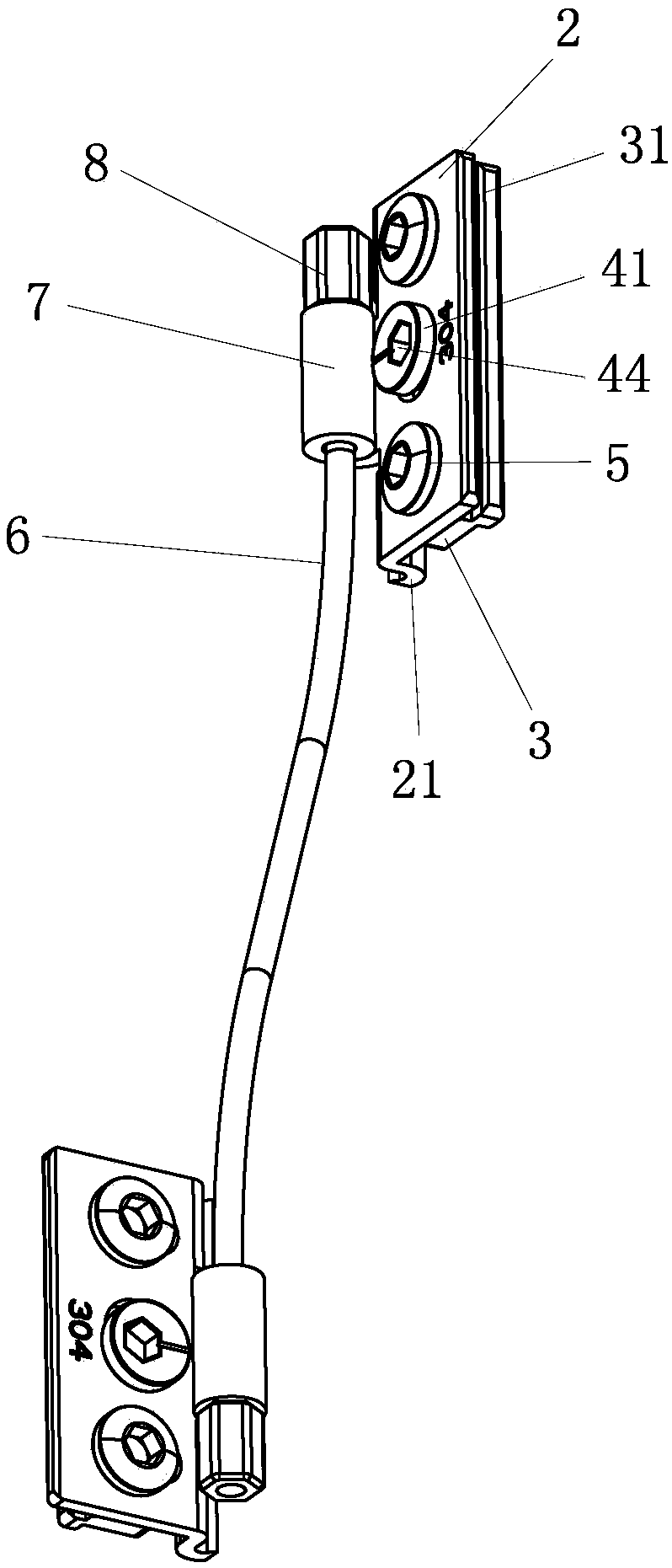
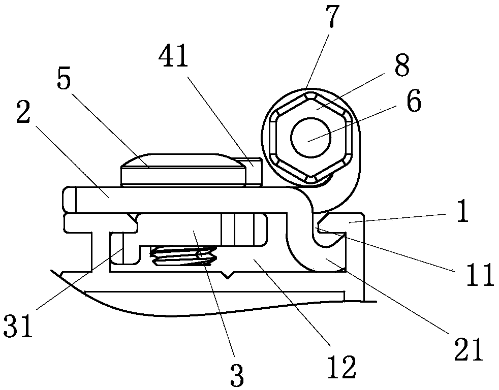
[0031] see Figure 1-Figure 8 , the easy-to-install push window fall prevention device includes two sets of fixing mechanisms respectively installed on the window frame and the window door installation rail 1, which includes the upper anti-fall plate 2 tightly pressed on the installation rail 1 and embedded installation The lower anti-fall plate 3 in the rail 1, the upper anti-fall plate 2 and the lower anti-fall plate 3 are provided with a driving device connecting the two and used to drive the lower anti-fall plate 3 to move outward and inward along its width direction 4.

[0032] The push-window anti-fall device can adjust the position of the lower anti-fall plate 3 through the driving device 4. During installation, the lower anti-fall plate 3 is retracted along its width direction through the drive device 4, and the push-window anti-fall device can be directly embedded into the installation In the rail 1, the driving device 4 is used to move the anti-fall plate 3 outward ...

no. 2 example

[0049] The difference between this easy-to-install anti-fall device for sliding windows is that the eccentric rivet is arranged on one side of the upper anti-fall plate 2, and the other side of the upper anti-fall plate 2 is provided with a locking screw 5, an eccentric rivet and a locking screw. 5 are arranged on the upper anti-fall plate 2 according to the left and right distribution. Compared with the first embodiment, this structure can reduce the use of one locking screw 5, and correspondingly reduce the upper anti-fall plate 2 and the lower anti-fall plate 3 The hole position on the top can also realize the adjustment function of the lower anti-fall plate 3 in the first embodiment and the function that the window anti-fall device is installed in the installation rail 1.

[0050] Other parts not described are the same as those of the first embodiment, and will not be discussed again.


PUM


Abstract

A sliding window anti-falling device easy to install comprises two fixing mechanisms which are installed on a window frame and a window installing rail correspondingly; each fixing mechanism comprisesan upper anti-falling plate which is tightly pressed on the installing rail, and a lower anti-falling plate which is embedded in the installing rail; and a driving device which is connected with eachupper anti-falling plate and the corresponding lower anti-falling plate and used for driving the lower anti-falling plate to move outwards or inwards in the width direction of the lower anti-fallingplate is arranged between the upper anti-falling plate and the lower anti-falling plate. According to the sliding window anti-falling device, the positions of the lower anti-falling plates can be adjusted through the driving devices, thus, the sliding window anti-falling device can be directly embedded in the installing rail, and installing is easy and convenient.

Description

technical field [0001] The invention relates to an easy-to-install anti-falling device for pushing windows. Background technique [0002] Chinese Patent Document No. CN206448688U disclosed a sliding window anti-fall device on August 29, 2017, including two mounting seats fixedly connected to the frame body and the door body of the sliding window respectively, and the anti-falling device bolted to the two mounting seats. Rope, the two mounting bases are a combination of the first mounting base and / or the second mounting base; the first mounting base is in the shape of a flat plate, and its edge is bent to form a first rope drum for the anti-fall rope to pass through; the first mounting base The seat is fixed to the frame body and / or door body through the second fastener; the second mounting seat includes an upper mounting plate (upper anti-fall plate) and a lower mounting plate (lower anti-fall plate), and the edge of the upper mounting plate is formed by bending The second ...

Claims


Application Information

Patent Timeline
Patent Type & Authority Applications(China)
IPC IPC(8): E05F7/00E06B3/36
CPCE05F7/00E06B3/36
Inventor 廖冠荣
Owner 佛山市顺德区勒流镇汇强金属制品有限公司
Why Eureka
Try Eureka