Small-pump strong-back-flow and large-pump single-outpouring type combined pump valve

A compound pump and large pump technology, which is applied in the direction of pumps, pump devices, pump components, etc., can solve the problems of reducing and losing a large number of injection channels and small amount of injection channels to prevent backflow and blockage, so as to reduce manufacturing costs, Effect of reducing wear and increasing service life

Active Publication Date: 2018-06-22
ZHENGZHOU SANHUA TECH & IND
View PDF8 Cites 1 Cited by
  • Summary
  • Abstract
  • Description
  • Claims
  • Application Information

AI Technical Summary

Problems solved by technology

However, when encountering a viscous fluid, when the compound pump injects the step, that is, when the valve core is in the initial position of closing the color paste injection, the color paste in the color paste bucket can be sucked into the compound pump or discharged from the compound pump. Press the color paste back into the color paste bucket, a considerable part of the viscous liquid flows back to the color paste bucket from the short circuit, but the viscous color paste does not pass through completely, or does not pass through a large number of injection channels and a small amount of injection channels state, which reduces or loses the anti-blocking effect of a large number of injection channels and a small amount of injection channels, so there is a risk of blockage of a large number of injection channels or a small amount of injection channels

Method used


Image

  • Small-pump strong-back-flow and large-pump single-outpouring type combined pump valve
  • Small-pump strong-back-flow and large-pump single-outpouring type combined pump valve
  • Small-pump strong-back-flow and large-pump single-outpouring type combined pump valve

Examples


Embodiment Construction

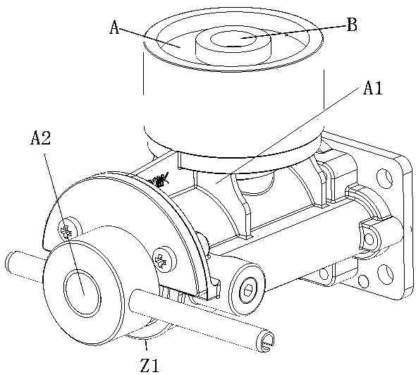
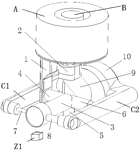
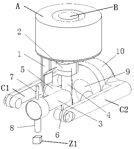
[0052] Below in conjunction with accompanying drawing, specific embodiment of the present invention is described in further detail:

[0053] Such as Figure 18-Figure 21 As shown, the small pump strong backflow large pump single-injection compound pump valve, the valve body is provided with a large pump inlet and outlet 60 and a small pump inlet and outlet 61, the shaft center passage 62 of the valve core is provided with a first radial passage 63 and a second radial passage 63 Two radial passages 64, one end of the axis passage 62 of the spool is also provided with an injection passage 65, the other end of the spool is provided with an inclined passage 66, and one end of the inclined passage 66 is connected to the color paste bucket inlet and outlet 67, wherein the pump When the valve is in the backflow state of the initial position, the axes of the large pump inlet and outlet 60, the small pump inlet and outlet 61, the first radial passage 63 and the second radial passage 64...


PUM


Abstract

The invention discloses a small-pump strong-back-flow and large-pump single-outpouring type combined pump valve. The combined pump valve comprises a large-small pump of a piston structure and a control valve, wherein the control valve is used for controlling the circulation of the large-small combined pump; the large-small pump of the piston structure is characterized in that a small pump cavity is arranged at the bottom end of an outlet in a large pump cavity, a small piston extends out of the end surface of a large piston in the large pump cavity, the small piston and the small pump cavity form a small pump, and a large pump and the small pump form the combined pump; and the control valve comprises a valve body and a valve element, wherein a valve element cavity for containing the rotaryvalve element is formed in the valve body, and the valve element is arranged in the valve element cavity. According to the combined pump valve, a large-volume outpouring channel and a small-volume outpouring channel are dredged by means of the strong pressure of the outpouring step of the combined pump, so that in the implementation step, supplementing can be timely carried out when the interiorof the combined pump is vacuum, and therefore the phenomenon that the interior of the combined pump waits for a long time for vacuum filling can be avoided.

Description

technical field [0001] The invention relates to the technical field of paint toning, in particular to a single-injection composite pump valve with strong backflow of a small pump and a single injection of a large pump. Background technique [0002] There are pump and valve structures already produced by our company, including large and small pumps with a plunger piston structure, valves for controlling the flow channels of large and small pumps, and a small pump cavity is installed at the bottom of the outlet of the large valve cavity, and extends inside the large pump cavity. A small piston is produced, and the small piston and the small pump cavity form a small pump, and the large pump and the small pump form a compound pump. The valve that controls the circulation of the large and small pumps includes such a flow structure. After the color paste pumped by the compound pump passes through the large amount of injection channel and the small amount of injection channel of th...

Claims


Application Information

Patent Timeline
Patent Type & Authority Applications(China)
IPC IPC(8): F04B15/02F04B23/06F04B53/10F04B53/16
CPCF04B15/02F04B23/06F04B53/10F04B53/16
Inventor 黄松王保松薛耀斌
Owner ZHENGZHOU SANHUA TECH & IND
Why Eureka
Try Eureka