
Speed reduction device

A technology of deceleration device and balance bar, which is applied in the direction of brake type, automatic brake, mechanical equipment, etc., and can solve the problems of parts throwing out and parts damage, etc.

Inactive Publication Date: 2018-06-22
宁波高新区神台德机械设备有限公司
View PDF9 Cites 2 Cited by
  • Summary
  • Abstract
  • Description
  • Claims
  • Application Information

AI Technical Summary

Problems solved by technology

[0003] The present invention intends to provide a deceleration device to solve the problems existing in the prior art that the rotating device connected to the motor may be damaged and thrown out due to too fast rotation

Method used


Image

  • Speed reduction device
  • Speed reduction device

Examples


Embodiment Construction

[0014] The present invention will be described in further detail below by means of specific embodiments:

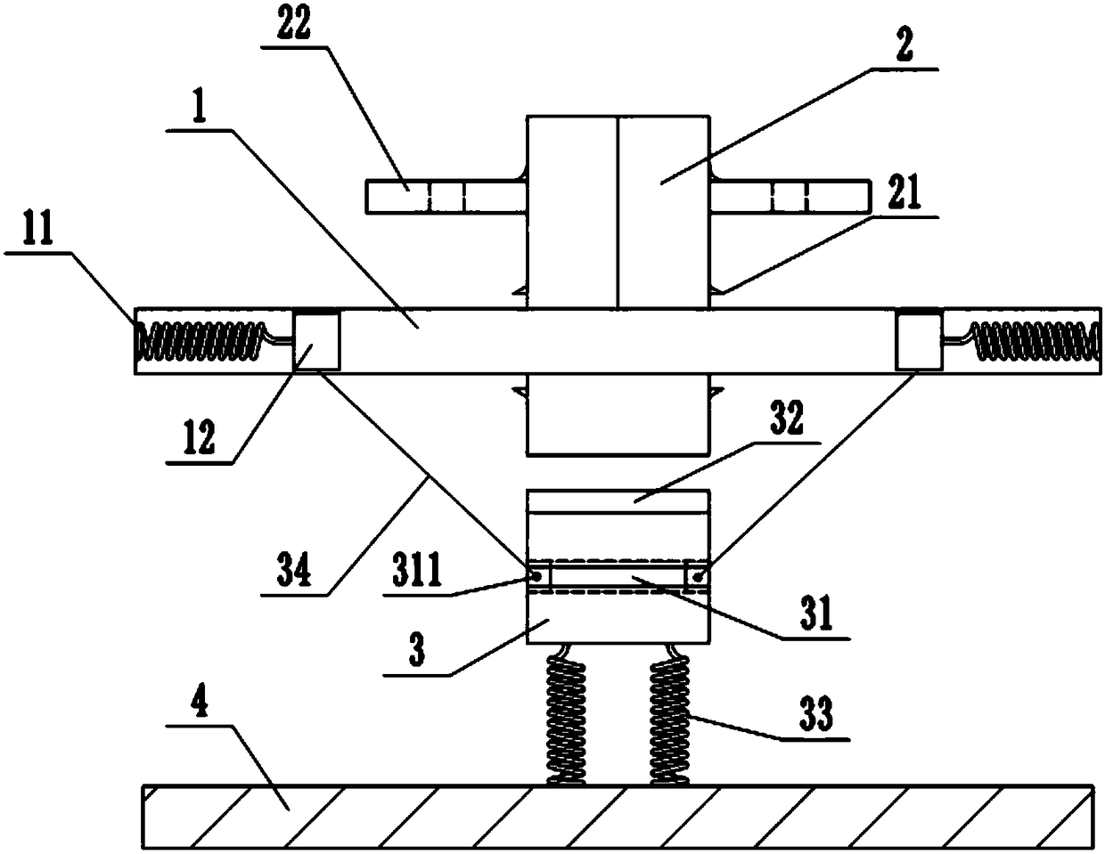
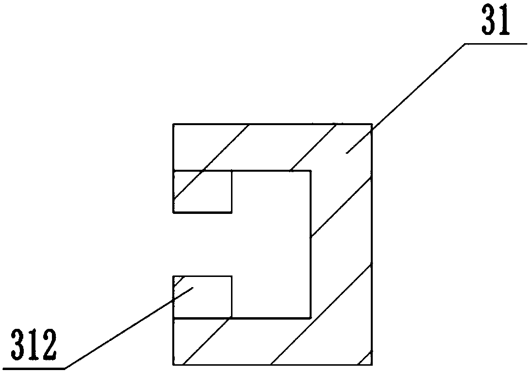
[0015] The reference signs in the drawings of the description include: balance bar 1, first spring 11, first slider 12, rotating rod 2, convex spine 21, flange 22, friction block 3, annular groove 31, second slider Block 311 , protrusion 312 , wear-resistant layer 32 , second spring 33 , rigid rope 34 , bottom plate 4 .

[0016] The embodiment is basically as attached figure 1 and figure 2 Shown: This solution is a speed reduction device, including a rotating mechanism and a friction mechanism. The rotating mechanism includes a balance bar 1 and a rotating bar 2. The balance bar 1 is hollow and has a long slit at the bottom. The balance bar 1 A first spring 11 is provided at both ends of the hollow interior, and a first slider 12 is connected to the first spring 11. The rotating rod 2 is arranged vertically through the balance rod 1, and the friction mechanism is locat...


PUM


Abstract

The invention relates to the field of transmission devices, in particular to a speed reduction device. The speed reduction device comprises a rotating mechanism and a friction mechanism. The rotatingmechanism comprises a balancing lever and a rotating lever, the balancing lever is hollow, the bottom of the balancing lever is provided with a long seam, first springs are arranged at the two ends ofthe hollow interior of the balancing lever, and each first spring is connected with a first sliding block. The rotating lever is perpendicularly arranged in a manner of penetrating the balancing lever. The friction mechanism is located below the rotating lever and comprises a friction block and second springs, the friction block is connected with a bottom plate through the second springs, the friction block is provided with an annular groove, second sliding blocks are arranged in the annular groove, and the second sliding blocks penetrate the long seam in the bottom of the balancing lever through rigid ropes and are connected with the first sliding blocks. The friction block is driven by centrifugal force of the first sliding blocks to move upwards, friction force is generated between thefriction block and the rotating lever, and thus the rotating speed is limited, and the problems that a rotating device connected to a motor may cause part damage and part throwing out due to too fastrotation are solved.

Description

technical field [0001] The invention relates to the field of transmission devices, in particular to a reduction device for speed control. Background technique [0002] In daily processing and production, the motor is widely used and is often used as an output device. However, the motor often rotates too fast because there is no speed limit setting when it is working, so that the rotating device connected to the motor also rotates too fast, resulting in the connection The rotating device on the motor may cause problems such as damage to parts and parts being thrown out due to too fast rotation. Contents of the invention [0003] The present invention intends to provide a deceleration device to solve the problems existing in the prior art that the rotating device connected to the motor may be damaged and thrown out due to too fast rotation. [0004] This solution is a speed reduction device, including a rotating mechanism and a friction mechanism. The rotating mechanism inc...

Claims


Application Information

Patent Timeline
IPC IPC(8): F16D59/00
CPCF16D59/00
Inventor 项文增
Owner 宁波高新区神台德机械设备有限公司
Learn More