A flexible gas sensor

A gas sensor and gas sensing technology, applied in the direction of instruments, scientific instruments, measuring devices, etc., can solve the problem that the gas sensor cannot be applied in a flexible state, and achieve the effect of real-time performance

Active Publication Date: 2020-10-13
泰州市海通资产管理有限公司
View PDF6 Cites 0 Cited by
  • Summary
  • Abstract
  • Description
  • Claims
  • Application Information

AI Technical Summary

Problems solved by technology

[0006] In order to solve the problem that the current gas sensor cannot be applied in a flexible state, the gas sensor can be made flexible, and the structure is improved and the cavity is set to realize the real-time interaction between the gas to be detected and the outside world, and provide gas sensing function for wearable devices The basis is provided, and the present invention provides a flexible gas sensor, which includes a flexible substrate, a gas sensor array, a gap and a cavity, a groove is formed in the flexible substrate, and the bottom and side walls of the groove form A rigid insulating layer, the elastic modulus of the rigid insulating layer is smaller than the elastic modulus of the flexible substrate, an array gas sensor is arranged on the rigid insulating layer at the bottom of the groove, and the array gas sensor includes a plurality of sensors arranged in an array Sensing site, a gap is formed above the gas sensing site of the array, there is a cover layer above the gap, a vent hole is arranged in the cover layer, and the cavity is provided in the flexible substrate on one side of the groove, There is a rigid insulating layer between the cavity and the groove, the cavity and the rigid insulating layer are separated by a part of the flexible substrate, and the rigid insulating layer and the flexible substrate between the cavity and the groove have through holes, The cavity changes in volume when the flexible substrate is deformed

Method used


Image

  • A flexible gas sensor
  • A flexible gas sensor

Examples


Embodiment Construction

[0017] In order to facilitate the understanding of the present invention, the present invention will be described more fully below with reference to the associated drawings. Preferred embodiments of the invention are shown in the accompanying drawings. However, the present invention can be embodied in many different forms and is not limited to the embodiments described herein. On the contrary, these embodiments are provided to make the understanding of the disclosure of the present invention more thorough and comprehensive.

[0018] The present invention will be further described in detail below in conjunction with the accompanying drawings and specific embodiments.

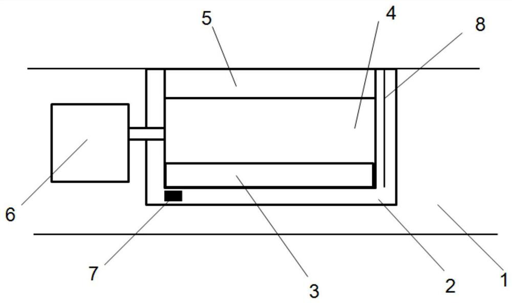
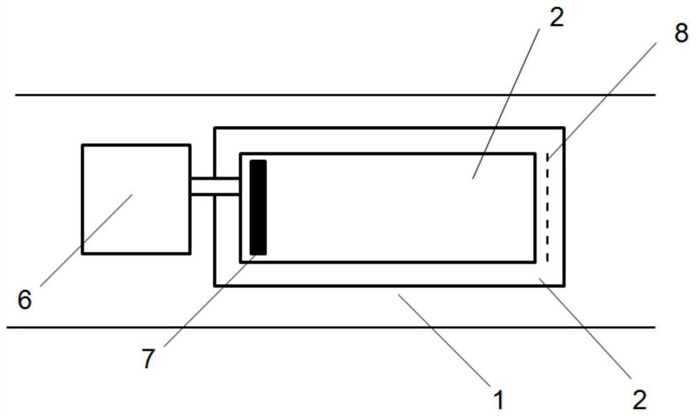
[0019] see figure 1 , figure 1 is a schematic diagram of the flexible gas sensor of the present invention, figure 2 It is a schematic top view of the flexible gas sensor of the present invention. The present invention provides a flexible gas sensor, which includes a flexible substrate 1, a gas sensing array,...


PUM


Abstract

The invention provides a flexible gas sensor which comprises a flexible substrate, a gas sensing array, gaps and cavities, wherein a groove is formed in the flexible substrate; a rigid insulating layer is respectively formed at the bottom and side walls of the groove; an array gas sensor is arranged on the rigid insulating layer at the bottom of the groove; the cavities are formed in the flexiblesubstrate on one side of the groove; the rigid insulating layer is separated from one part of the flexible substrate between the cavity and the groove; the rigid insulating layer and the flexible substrate between the cavity and the groove partially have through holes; the cavities change in volume when the flexible substrate is deformed. The flexible gas sensor solves a problem that a current gassensor cannot be applied in a flexible state, allows gas sensors to have flexibility, realizes real-time interaction between a gas to be detected and the outside by improving a structure and arranging the cavities, and provides a basis for providing a gas sensing function for wearable equipment.

Description

technical field [0001] The invention belongs to the technical field of gas sensors, in particular to a flexible gas sensor. Background technique [0002] During the past fifty years, various technical branches of gas sensing technology have been established through different studies. At present, the most common gas sensing technology is the sensing technology based on metal oxide semiconductor, which has many advantages such as low cost and simple manufacture. However, this type of technology needs to heat the sensor to a certain high temperature environment through a special micro-hot plate structure to work, which requires more cost and complicated structure compared with some sensors that work at room temperature, which limits this type of technology. sensor development. This has also prompted researchers to develop new gas-sensing materials based on novel composite materials with lower power consumption and better chemical selectivity. [0003] Carbon nanotubes have b...

Claims


Application Information

Patent Timeline
Patent Type & Authority Patents(China)
IPC IPC(8): G01N27/00
CPCG01N27/00
Inventor 胡静
Owner 泰州市海通资产管理有限公司
Why Eureka
Try Eureka