
Accurate calibration method of image surface of optical camera

An optical camera and calibration method technology, applied in image analysis, image data processing, instruments, etc., can solve the problems of uniform field manufacturing difficulty, unfavorable engineering application, affecting display effect, etc., and achieve great scientific and engineering application value and application value. High, breaking through the technical bottleneck effect

Active Publication Date: 2018-06-22
CHANGCHUN CEDAR ELECTRONICS TECH CO LTD
View PDF4 Cites 13 Cited by
  • Summary
  • Abstract
  • Description
  • Claims
  • Application Information

AI Technical Summary

Problems solved by technology

However, the industrial camera or SLR camera used for calibration is not a standard luminance measurement instrument and has not been strictly calibrated. Therefore, during the image acquisition process, due to factors such as lens distortion and camera vignetting, there are serious curved surfaces in the acquired image. Phenomenon, which greatly affects the display effect after correction
[0004] In order to solve the above problems, although the uniform field calibration method mainly used at present can effectively correct the acquisition surface of the camera, the manufacturing of the uniform field is difficult and expensive, which is not conducive to engineering applications; while other methods cannot correct the surface well
Therefore, the camera acquisition surface becomes a difficult problem of acquisition correction

Method used


Image

  • Accurate calibration method of image surface of optical camera

Examples


Embodiment Construction

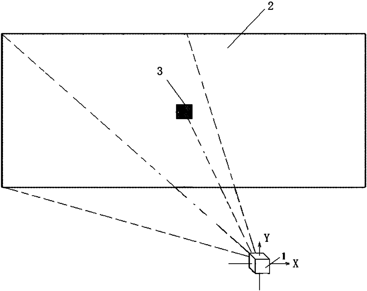
[0031] Such as figure 1 As shown, a calibration target 3 with constant brightness is fixed in the center of the display screen 2, and the calibration target 3 contains a single or multiple red, green and blue three-color light-emitting chips; the camera 1 is fixed on a platform with two degrees of freedom, Camera 1 can perform pitch rotation around the X-axis and azimuth rotation around the Y-axis on the gimbal; when camera 1 returns to the zero position, the pitch angle and azimuth angle are both zero, and the lens of camera 1 is facing the display screen 2 at this time The center normal direction of . Described camera 1 adopts CMOS type or CCD scientific type or industrial type camera, also can adopt single-lens reflex civilian camera and mobile phone.

[0032] Since the effective viewing angle of camera 1’s effective field of view in the horizontal direction is generally within ±20°, the angle step range of the control pan / tilt in the effective field of view in the horizon...


PUM


Abstract

The invention relates to an accurate calibration method image surface of optical camera. The method is as follows: fixing a calibration target with constant brightness at a screen center of a displayscreen; the camera is fixed on the tripod head, the calibration target is lightened so that the image formed on the effective field of view of the camera is a light spot; rotating the camera accordingto a preset angle step by a tripod head control camera, collecting the intensity data of the spot each time and recording the corresponding camera pitch angle and the azimuth data so as to obtain theeffective field-of-view brightness surface of the camera; and compensating the curved surface to obtain the effective field-of-view brightness plane after the camera calibration. The invention solvesthe problem of accurate calibration of the effective field-of-view image surface of the optical camera, has the advantages of simple method and low cost, breaks the technical bottleneck of the calibration of the effective field-of-view image surface of the optical camera, can finish the optical plane calibration of the application of the large-field-of-view engineering application and has high application value.

Description

technical field [0001] The invention belongs to the technical field of acquisition and correction of LED display screens, and relates to a method for accurately demarcating curved surfaces of images acquired by an optical camera. Background technique [0002] With the rapid development of the LED display field, the application requirements of the LED display screen are also emerging, and the display effect of the LED display screen has become one of the important factors restricting the development of the LED display field. Due to the discreteness and attenuation of light-emitting diodes, the LED display has the problem of uneven brightness display, which seriously affects the display effect. In order to overcome this problem, the point-by-point brightness correction technology of LED display screens emerged at the historic moment, and developed rapidly, which greatly improved the display quality. [0003] At present, the LED point-by-point correction technology that is mai...

Claims


Application Information

Patent Timeline
Patent Type & Authority Applications(China)
IPC IPC(8): G06T7/80G05D3/12
CPCG05D3/12G06T7/80
Inventor 苗静郑喜凤刘双双王平丁铁夫
Owner CHANGCHUN CEDAR ELECTRONICS TECH CO LTD
Learn More