
Method for achieving positioning by using wheel type odometer-IMU and monocular camera

An -IMU, odometer technology, applied in the field of computer vision, can solve the problems of inertial measurement unit unable to detect acceleration, scale uncertainty increases, positioning error increases, etc., to achieve low cost, solve scale uncertainty, accurate high sex effect

Active Publication Date: 2021-04-30
SOUTH CHINA UNIV OF TECH
View PDF7 Cites 4 Cited by
  • Summary
  • Abstract
  • Description
  • Claims
  • Application Information

AI Technical Summary

Problems solved by technology

[0003] However, there are still some problems in the scheme of directly using visual inertia on ground vehicles. When the vehicle moves at a constant speed, the inertial measurement unit cannot detect the acceleration, which causes the scale uncertainty to increase at this time, which in turn leads to scale drift and positioning error. big

Method used


Image

  • Method for achieving positioning by using wheel type odometer-IMU and monocular camera
  • Method for achieving positioning by using wheel type odometer-IMU and monocular camera
  • Method for achieving positioning by using wheel type odometer-IMU and monocular camera

Examples


Embodiment Construction

[0079] Embodiments of the present invention are described below through specific examples. It should be noted that the diagrams provided in this embodiment only illustrate the basic idea of ​​the present invention in a schematic manner, so only the relevant aspects of the present invention are shown in the drawings. The components are not drawn according to the number, shape and size of the components in actual implementation. The type, quantity and proportion of each component in actual implementation can be changed arbitrarily, and the layout of the components may also be more complicated.

[0080] The present invention will be described in detail below in conjunction with the embodiments and the accompanying drawings.

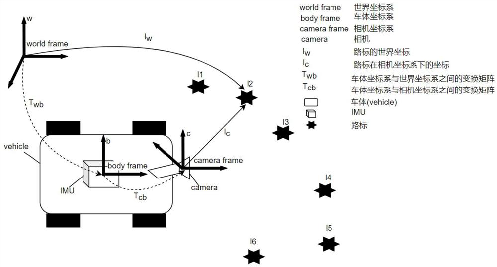
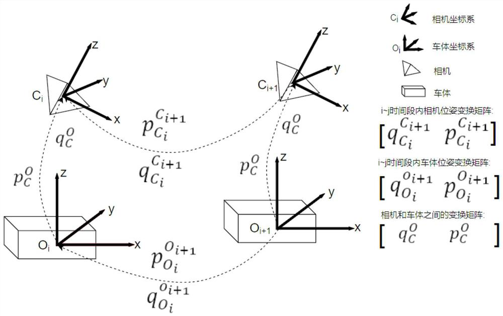
[0081] A system that uses a wheel odometer-IMU and a monocular camera to realize a positioning method, including a front-end VO module, a back-end image optimization module, and a loop detection module. The front-end VO module is used to predict the prelimin...


PUM


Abstract

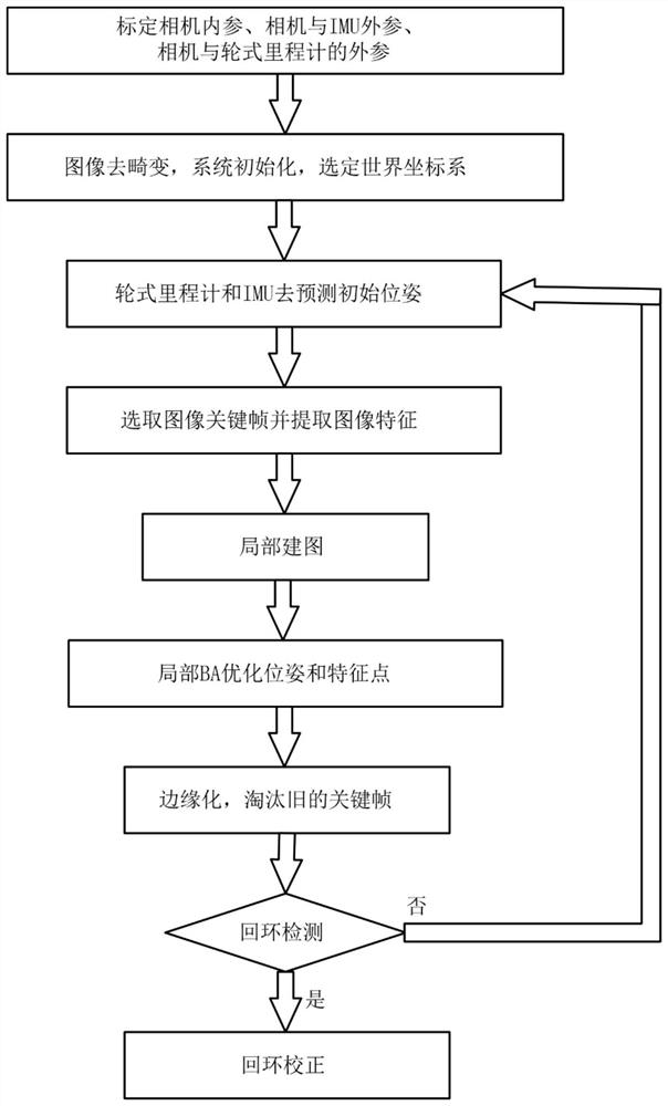
The invention discloses a method for achieving positioning by using a wheel type odometer IMU and a monocular camera. The method mainly comprises the following steps: (1) calibrating camera internal parameters, camera and wheel type odometer external parameters, and IMU and camera external parameters; (2) selecting an image key frame from an image shot by a camera, correcting distortion of the image, extracting feature points, performing system initialization, and finally selecting a current frame pose when initialization succeeds as a pose of a world coordinate system; (3) projecting the map point to the plane image according to the estimated value of the vehicle body pose; (4) predicting the pose of the vehicle body; (5) establishing a local map; (6) establishing an optimization problem about all poses and map points of the vehicle body according to the local map, and then obtaining the optimized poses and map points through a bundle adjustment method; and (7) detecting loopback by adopting a bag of words (BoW), and performing loopback correction once detecting that the same position is passed.

Description

technical field [0001] The invention belongs to the technical field of computer vision, and mainly studies a method for realizing positioning by using a wheel-type odometer-IMU and a monocular camera. Background technique [0002] With the development of SLAM technology, the positioning and navigation of ground vehicles began to realize positioning by laying some media on the ground (such as magnetic tracks, RFID, etc.), such as [Zhang Chenbeixi, Huang Zhiqiu, A review of the development of automatic guided vehicles (AGV)[J] Information Technology Application. 2010.], and now it is gradually changing to a trackless positioning method. Due to the relatively low cost of the camera and the images it captures can provide rich information, more and more attention has been paid to using visual SLAM (simultaneous localization and mapping) to achieve positioning and navigation, and many visual SLAM solutions have emerged, such as RGB_D-based cameras The SLAM scheme RGB_D-SLAM [Enge...

Claims


Application Information

Patent Timeline
Patent Type & Authority Applications(China)
IPC IPC(8): G06T7/73G06T7/80G06T5/00G06K9/62G06F16/29G01C21/16
CPCG06T7/74G06T7/80G06F16/29G01C21/165G06T2207/20081G06T2207/30204G06T2207/30244G06T2207/30248G06F18/22G06F18/23213G06F18/24G06F18/214G06T5/80Y02T10/40
Inventor 宋高高哀薇熊彪
Owner SOUTH CHINA UNIV OF TECH
Learn More