
A fixture device for pressing PCB

A fixture device and matching block technology, applied in the direction of laminating printed circuit boards, assembling printed circuits with electrical components, printed circuits, etc., can solve the problems of increasing material costs and production costs, different positions of pressing areas, etc., to save materials. , The effect of smart design and easy operation

Active Publication Date: 2020-01-14
星源电子科技(深圳)有限公司
View PDF5 Cites 0 Cited by
  • Summary
  • Abstract
  • Description
  • Claims
  • Application Information

AI Technical Summary

Problems solved by technology

Since the PCB has different lengths and widths, and the component areas are different, the position and length of the FPC pressing area are also different. In this way, a set of corresponding pressing fixtures need to be prepared every time a different model is made, which increases the cost of materials and production cost etc.

Method used


Image

  • A fixture device for pressing PCB
  • A fixture device for pressing PCB
  • A fixture device for pressing PCB

Examples


Embodiment Construction

[0019] The implementation structure of the present invention will be described below in conjunction with the accompanying drawings.

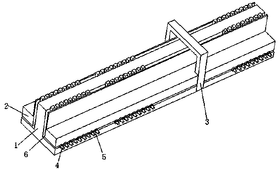
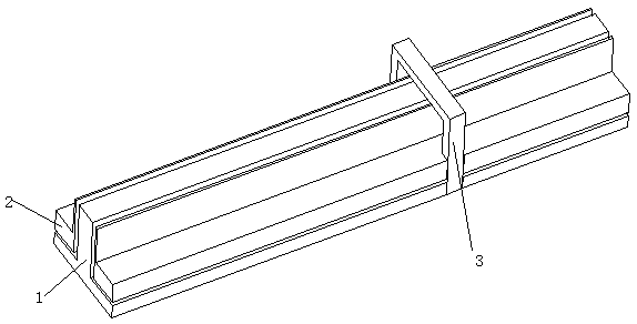
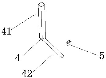
[0020] Such as Figure 1 to Figure 5 As shown, the fixture device for pressing PCB of the present invention includes a main body block 1, a mating block 2, a fixed block 3, an L-shaped support 4 and a nut 5; the main body block 1 is T-shaped, and the mating block 2 is set There are two pieces, symmetrically arranged on both sides of the main block 1; the main block 1 and the matching block 2 are connected and fixed by the fixing block 3, and an L-shaped sliding channel 6 is formed between the main block 1 and the matching block 2; the sliding channel 6 can accommodate a plurality of L-shaped supports 4, the vertical length and horizontal length of the L-shaped support 4 are respectively greater than the vertical length and the horizontal length of the sliding channel 6; the L-shaped support 4 is composed of a cuboid 41 and The other end is inte...


PUM


Abstract

The invention discloses a PCB stitching clamp device, which comprises a main body block, cooperation blocks, a fixation block, L-shaped supports and nuts. The main body block is in T shape; the two cooperation blocks are symmetrically arranged at the two sides of the main body block; the main body block and the cooperation blocks are fixedly connected through the fixation block; an L-shaped sliding channel is formed between the main body block and the cooperation blocks; the sliding channel can accommodate the plurality of L-shaped supports; the vertical length and horizontal length of the L-shaped supports are larger than the vertical length and horizontal length of the sliding channel; each L-shaped support is formed by integrating a cuboid at one end and a cylinder body with a thread atthe other end; and the L-shaped supports are in thread connection cooperation alignment with a PCB stitching area through the nuts. The PCB stitching clamp device can cooperatively stitch PCBs in various different lengths and widths, different component positions and different stitching areas by adjusting the position and quantity of the L-shaped supports, is good in clamping effect, is simple instructure, is clever in design, saves materials and is convenient to operate.

Description

technical field [0001] The invention relates to the technical field of fixtures in the production process of electronic products, in particular to a fixture device for pressing PCBs. Background technique [0002] The press-fit PCB fixture is used to place a PCB in the early stage. It is required that the surface of the fixture has high and low surfaces. The high surface supports the press-fit FPC area of ​​the PCB without components, and the low surface is used to avoid the component area. After the PCB board is fixed, the operating machine passes two probes to align the alignment MARK PAD on the PCB, and then lowers the cutter head to press the FPC and PCB together. Since the PCB has different lengths and widths, and the component areas are different, the position and length of the FPC pressing area are also different. In this way, a set of corresponding pressing fixtures need to be prepared every time a different model is made, which increases the cost of materials and pr...

Claims


Application Information

Patent Timeline
Patent Type & Authority Patents(China)
IPC IPC(8): H05K3/00H05K3/36
CPCH05K3/00H05K3/0058H05K3/36H05K3/361
Inventor 刘洪王惠奇
Owner 星源电子科技(深圳)有限公司
Learn More