Foldable guide rail tracks for elevator systems
A technology of folding guide rails and elevator systems, which is applied in transportation, packaging, elevators, etc., can solve the problems of time-consuming and labor-intensive guide rails, and achieve the effect of easy installation
- Summary
- Abstract
- Description
- Claims
- Application Information
AI Technical Summary
Problems solved by technology
Method used
Image

Examples
Embodiment Construction
[0030] The various features of the disclosure will be presented as shown and described herein. Various embodiments may have the same or similar features, and thus the same or similar features may be labeled with the same reference symbols, but preceded by a different first numeral to indicate the figure in which the feature is shown. Thus, for example, element "a" shown in Figure X could be labeled "Xa" and a similar feature in Figure Z could be labeled "Za". Although like reference symbols may be used in a general sense, various embodiments will be described and various features may include changes, alterations, modifications, etc., whether described explicitly or otherwise, as would be understood by those skilled in the art. understood by those skilled in the art.
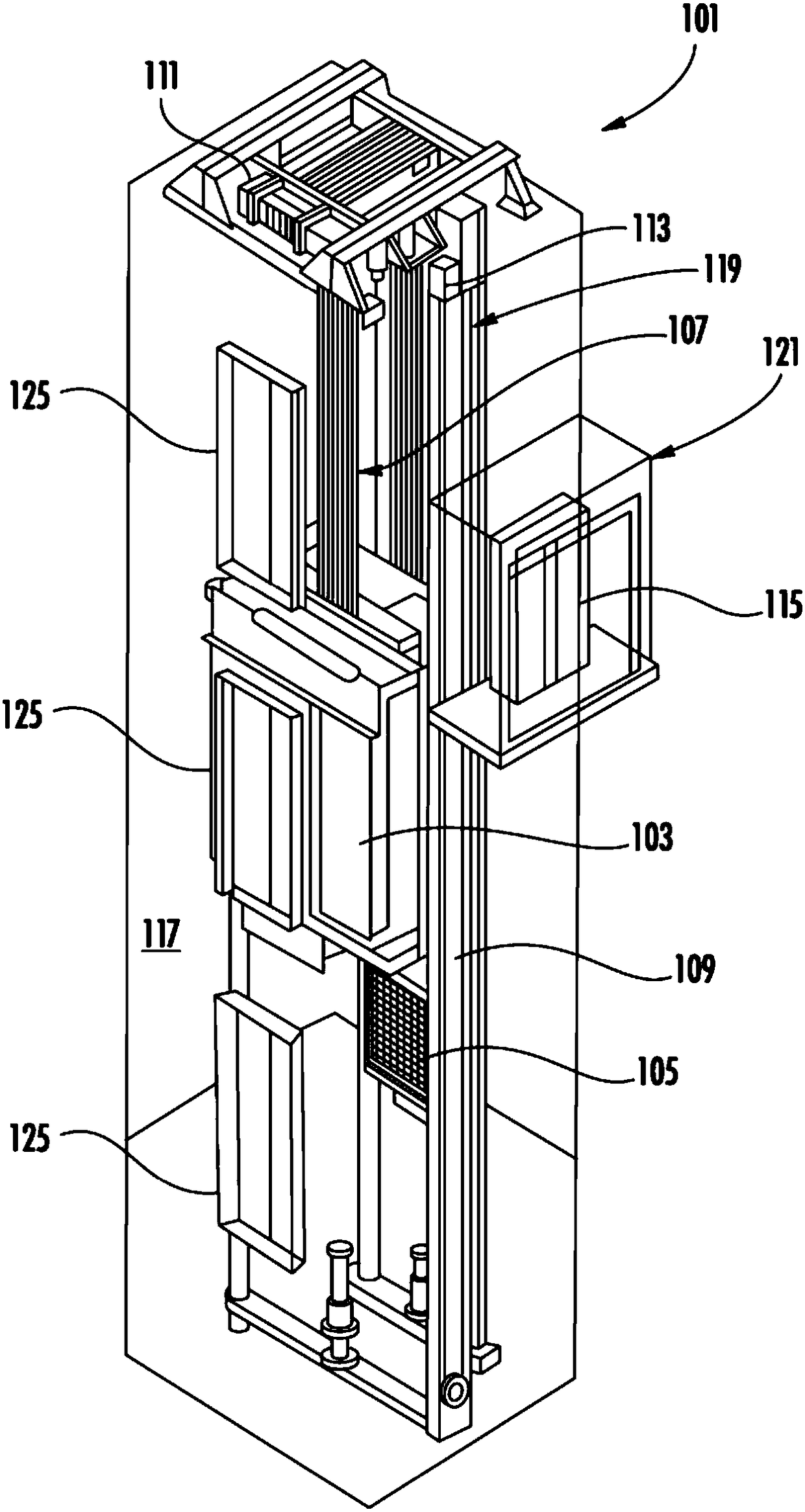
[0031] Figure 1A is a perspective view of an elevator system 101 comprising an elevator car 103, counterweight 105, roping 107, guide rails 109, machine 111, position encoder 113 and controller 115. The elevat...
PUM
 Abstract
Description
Claims
Application Information