Gravity lever power generator
A technology of generators and levers, applied in the direction of engines, machines/engines, electrical components, etc., can solve the problems of long-term use and high cost of wiring
- Summary
- Abstract
- Description
- Claims
- Application Information
AI Technical Summary
Problems solved by technology
Method used
Image

Examples
Embodiment 1
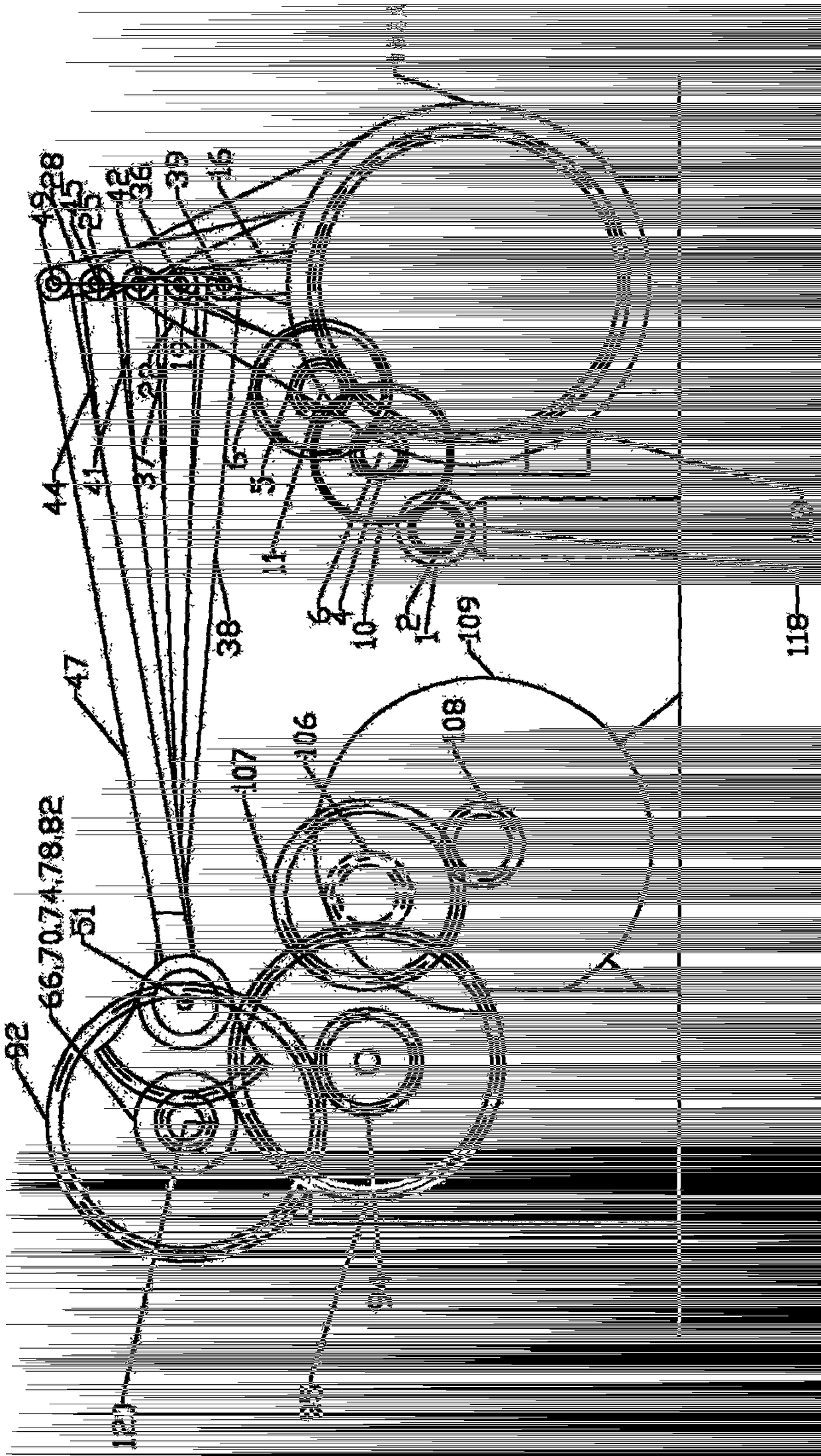
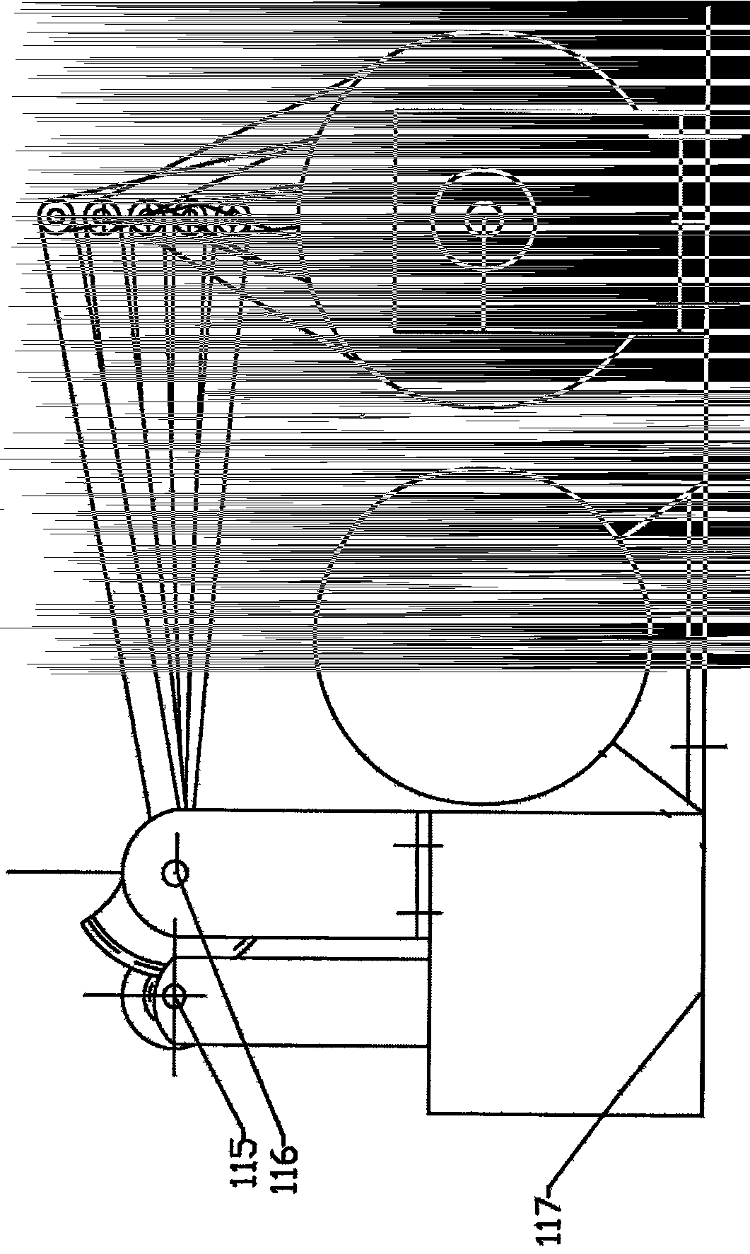
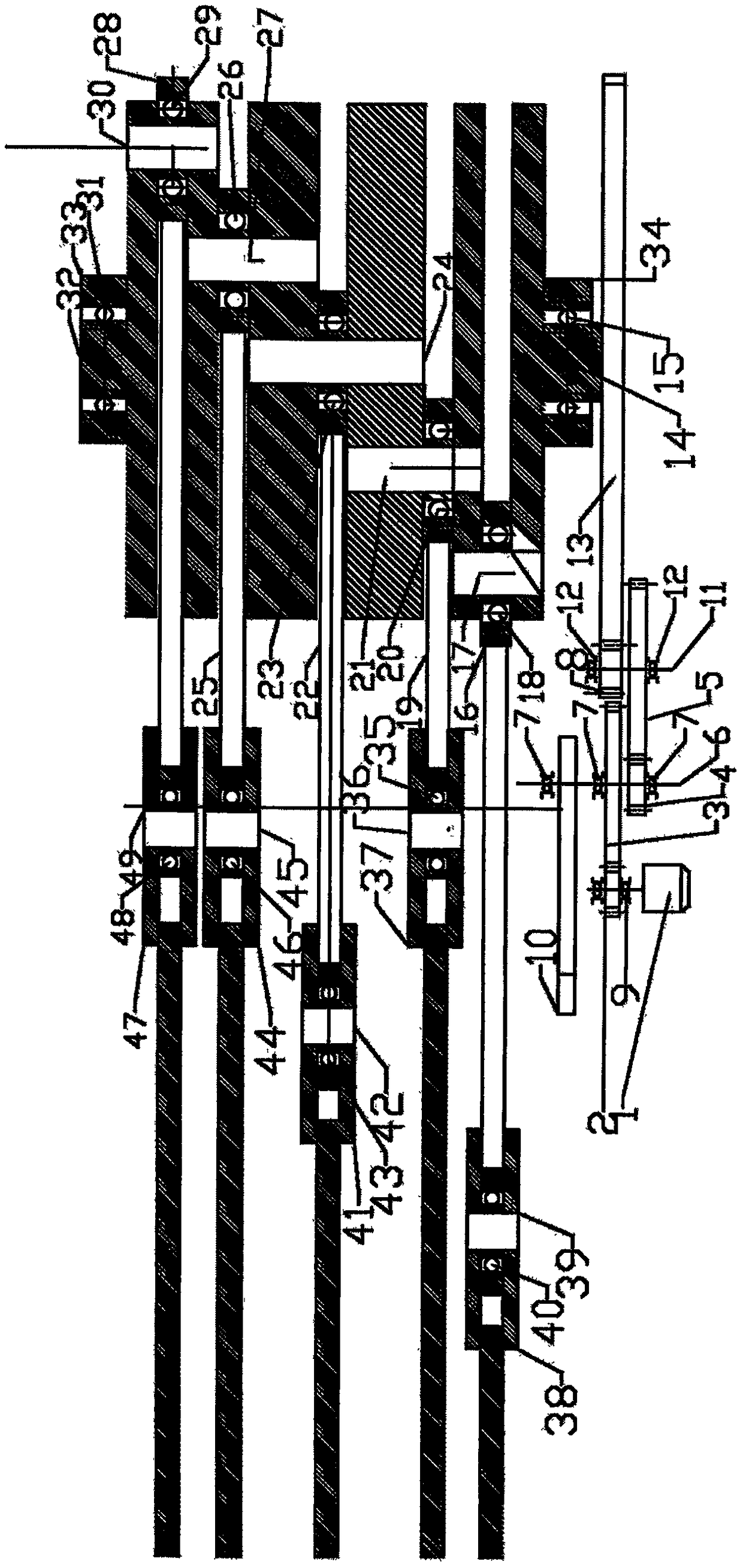
[0029] Such as Figure 1-Figure 6 As shown, the application discloses a gravity lever power generator, including a starter motor 1, the starter motor 1 meshes with the bridge reduction gear 3 through the start pinion 2, and the bridge reduction gear 3 is connected to the reduction center shaft 6 through a spline. Gears 3, 4 and center of gravity flywheel 10, bridge reduction gears 5, 8 are connected by splines on the secondary reduction shaft 11, bridge reduction gear 4 meshes with bridge reduction gear 5, bridge reduction gear 8 and crankshaft starting gear 13 meshes, crankshaft starting gear 13 is connected with crankshaft 14 by spline, and crankshaft 14 is connected with lever 37,38,41,44,47 respectively through crankshaft connecting rod 16,19,22,25,28, and described lever 37 , 38, 41, 44, 47 are respectively connected with the automatic locking positioning plate 60, 61, 62, 63, 64 through the lever center bearing 53, 54, 55, 56, 57 connected to the lever fulcrum center sha...
Embodiment 2
[0040] As can be seen from the accompanying drawings, a chassis 117 is provided at the bottom, and a starter motor 1 is fixed on the chassis. The starter motor 1 is connected to the starter pinion 2, and the starter pinion 2 meshes with the bridge reduction gear 3 and the bridge reduction gear 4, and the deceleration center of gravity The shaft 6 and the primary bridge bearing seat 7 support and connect the center of gravity flywheel 10 to increase power. The bridge reduction gear 4 meshes with the bridge reduction gear 5, and the bridge reduction gear 5 is transmitted to the bridge reduction gear 8, and the center of gravity shaft 6 is decelerated. Fixed on the bridge bearing seat 7, the reduction shaft 11 is fixed on the bearing seat 12, the bridge bearing seat 7 and the bearing seat 12 are fixed on the chassis 117, the bridge reduction gear 8 meshes with the crankshaft starting gear 13, the crankshaft starting gear 13 and the crankshaft 14 are fixedly connected, crankshaft b...
PUM
 Abstract
Description
Claims
Application Information
 - R&D
- Intellectual Property
- Life Sciences
- Materials
- Tech Scout
- Unparalleled Data Quality
- Higher Quality Content
- 60% Fewer Hallucinations
Browse by: Latest US Patents, China's latest patents, Technical Efficacy Thesaurus, Application Domain, Technology Topic, Popular Technical Reports.
© 2025 PatSnap. All rights reserved.Legal|Privacy policy|Modern Slavery Act Transparency Statement|Sitemap|About US| Contact US: help@patsnap.com