Macro-zoom optical system

An optical system and macro technology, applied in the field of macro zoom optical system, can solve the problems that affect the user's sensory effect

Active Publication Date: 2018-06-26
JIAXING ZHONGRUN OPTICAL TECH
View PDF1 Cites 2 Cited by
  • Summary
  • Abstract
  • Description
  • Claims
  • Application Information

AI Technical Summary

Problems solved by technology

However, when the focal length of the zoom lens is increased, the F value will also increase synchronously, and the F value directly determines the illumination of the picture...

Method used


Image

  • Macro-zoom optical system
  • Macro-zoom optical system
  • Macro-zoom optical system

Examples


Embodiment 1

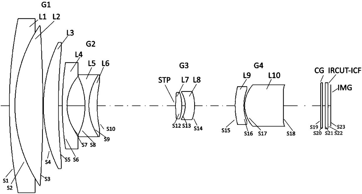
[0032] Such as figure 1 As shown, this embodiment sequentially includes from the object side to the image side: a first lens group G1 with positive refractive power, a second lens group G2 with negative refractive power, a third lens group G3 with positive refractive power, and The fourth lens group G4 with positive refractive power and the light receiving surface IMG, wherein: the first lens group and the third lens group are fixed groups, the second lens group is a zoom group, and the fourth lens group is a focus group.

[0033] A protective glass CG and an infrared cut filter IRCUT-ICF for filtering unnecessary light and stray light are arranged between the fourth lens group G4 and the sensor IMG.

[0034] The light receiving surface IMG is provided with solid-state imaging elements such as CCD and CMOS.

[0035] The first lens group G1 includes in order from the object side: a first lens L1 with positive refractive power, a second lens with negative refractive power L2, and a thi...

Embodiment 2

[0052] Such as Figure 4 As shown, compared with Embodiment 1, the first lens group G1 in this embodiment sequentially includes from the object side: a first lens L1 with positive refractive power, a second lens L2 with negative refractive power, and a positive refractive power A third lens L3 with a degree of power and a fourth lens L4 with positive refractive power, wherein the second lens L2 is cemented with the third lens L3.

[0053] The second lens group G2 includes in order from the object side: a fifth lens L5 with negative refractive power, a sixth lens L6 with negative refractive power, and a seventh lens L7 with positive refractive power.

[0054] The third lens group G3 includes, from the object side, an eighth lens L8 with positive refractive power and a ninth lens L9 with negative refractive power. The front surface of the eighth lens L8 is set as an aperture stop STP.

[0055] The fourth lens group G4 includes in order from the object side: a tenth lens L10 with negati...


PUM


Abstract

The invention relates to a macro-zoom optical system, in particular to a macro-lens with an inner focusing structure. The macro-zoom optical system sequentially comprises a first lens group with positive focal power, a second lens group with negative focal power, a third lens group with positive focal power, a fourth lens group with positive focal power, and a light receiving surface from the object side to the image side; the first lens group and the third lens group are fixed groups, the second lens group is a zoom group, and the fourth lens group is a focusing group; the second lens group is moved back and forth along the optical axis direction so as to realize zoom from the wide angle end to the telescope end; the fourth lens group is moved towards the object side along the optic axisdirection, so as to correct the soft focus due to zooming process and change of object distance. The macro-zoom optical system has the advantages that the glass with extra low dispersion is not contained, the weight is light, the size is small, the F value is constant in the zoom process from the wide angle end to the telescope end, and various aberrations can be well compensated in the whole-focus range.

Description

Technical field [0001] The invention relates to a technology in the field of optical devices, in particular to a macro zoom optical system that does not contain ultra-low dispersion glass, is light and small, and can maintain a constant F value. Background technique [0002] The existing macro lens usually achieves focusing on a close-up object through the front and back expansion of the first lens group closest to the object side. Limited by the height of light and the angle of view, the front group lens is often the lens group with the largest aperture. Due to the front group telescopic focusing method, a large-volume high magnetic motor must be used to ensure the automatic focusing speed. The focusing characteristics of the focus group make the size of the entire movement stroke must be able to accommodate the aperture of the group, and the lens volume cannot be compressed; [0003] Because optical lenses have different refractive indexes for different colors of light, chromati...

Claims


Application Information

Patent Timeline
IPC IPC(8): G02B15/173
CPCG02B15/173
Inventor 厉冰川张师朋尚洁阳盛亚茗
Owner JIAXING ZHONGRUN OPTICAL TECH
Why Eureka
Try Eureka