
Reduced-pressure distillation equipment for pretreatment of waste lubricant oil

A technology for distillation equipment and waste lubricating oil, which is applied in the direction of lubricating oil distillation, distillation control/regulation of hydrocarbon oil, hydrocarbon distillation, etc., and can solve the problem of increased internal pressure, coking, and reduced equipment operating efficiency and production capacity of equipment or vacuum towers and other issues, to achieve the effect of improving efficiency and high-efficiency refining effect

Pending Publication Date: 2018-06-29
深圳至诚环境科技有限公司
View PDF2 Cites 4 Cited by
  • Summary
  • Abstract
  • Description
  • Claims
  • Application Information

AI Technical Summary

Problems solved by technology

[0010] However, in actual production, in the equipment including trays, trays and packing, long-term accumulation of distillate oil will cause pipe hole blockage, plate corrosion and other phenomena; and the equipment and operation of the above-mentioned patents have not effectively Solve the coking phenomenon in the tower (including around the tower and the bottom of the tower) during the refining process of the vacuum tower
Not only the trays form coking during long-term operation, but other parts of the tower also form coking phenomena in other positions of the tower (such as the bottom of the tower, the side of the tower) during the operation due to the setting of the trays, which will affect The efficiency of gas-liquid mass transfer and heat transfer will reduce the separation effect of distillates. In severe cases, it will cause the internal pressure of equipment or decompression tower to increase, and there will be complete hidden dangers.
Moreover, after the equipment of the related art has been in operation for a period of time, the operation of the equipment usually has to be stopped to remove the accumulated coke, which undoubtedly reduces the operating efficiency and production capacity of the equipment

Method used


Image

  • Reduced-pressure distillation equipment for pretreatment of waste lubricant oil
  • Reduced-pressure distillation equipment for pretreatment of waste lubricant oil
  • Reduced-pressure distillation equipment for pretreatment of waste lubricant oil

Examples


Embodiment 1

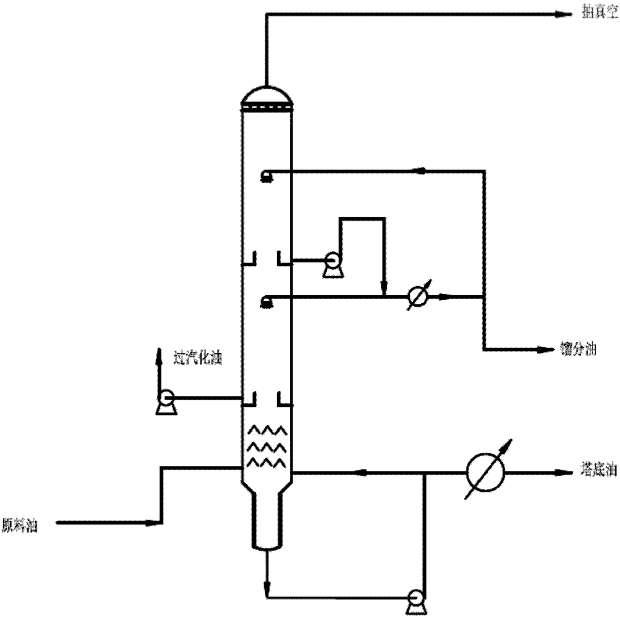
[0051] The structure of the present embodiment decompression tower is as figure 1 , in the present embodiment, after the waste oil entering the feed port is vaporized, it passes through the refining process of the distillate rectification section (1 rectification section), and the obtained distillate is carried out through the oil collection tank below the sprayer. Pull out collection.

[0052] In this embodiment, no filler is used, and the rectification part and rectification section only adopt the shower structure to carry out the rectification process.

[0053] The specific operation process is as follows:

[0054] The waste lubricating oil is heated in the heating furnace (the heating furnace is not shown), and the waste lubricating oil heated by the heating furnace enters the decompression tower through the oil transfer line arranged between the heating furnace and the decompression tower.

[0055] Then in the decompression tower, a high-vacuum spray fractionation proce...

Embodiment 2

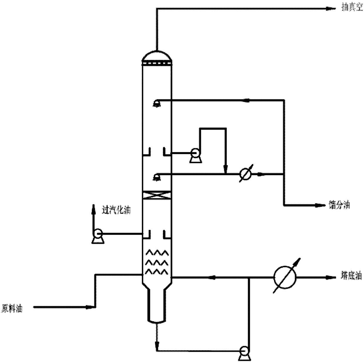
[0065] The technical scheme of this specific embodiment is substantially the same as that of Example 1, except that a section of packing is added below the shower. The setting of this section of filler can further assist in enhancing the effect of rectification. In this embodiment, sprayers are still used to replace trays and trays. In the waste lubricating oil pretreatment decompression tower of this embodiment, high vacuum and low pressure drop are still used in the decompression tower, so that the sprayed droplets Fully disperse and directly contact with the updraft for heat and mass exchange, and realize the residual pressure at the top of the device below 30mmHg, which reduces the use of trays in the vacuum tower, simplifies equipment, controls pressure drop, and prevents coking to a large extent. Effect.

Embodiment 3

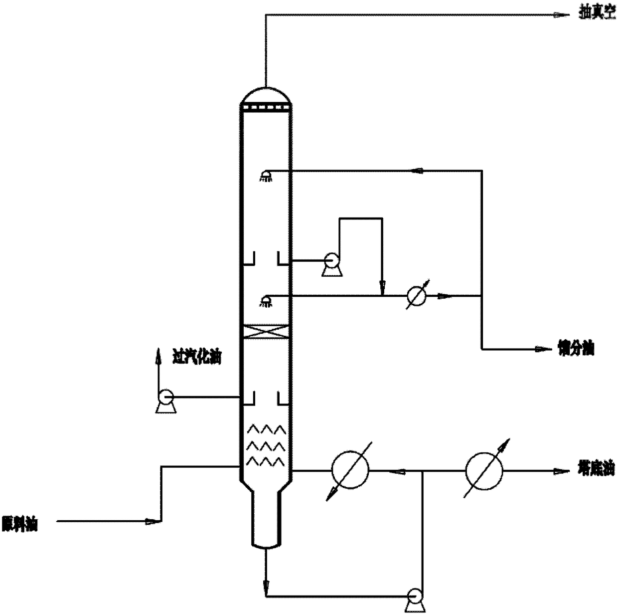
[0067] In this embodiment, after the waste oil entering the feed port is vaporized, it sequentially passes through the over-vaporized oil recovery section, including a packing section and a distillate oil recovery section. For details, please refer to image 3 .

[0068] Firstly, different from Embodiment 1, Embodiment 3 also sets a section of packing under the sprinkler. After the packing section is set, the present embodiment still adopts the shower to replace the tray and the tray. In addition, different from the examples 1 and 2, the present embodiment adopts a further step for the circulation of the bottom oil. craft. Specifically, after the tower bottom oil is released from the bottom of the tower, it is pumped and first passed through the bottom oil reheater ( image 3The component on the upper left of the middle tower bottom oil pump represents the reheater), which is recirculated back into the tower. The setting of the reheater can make up for the insufficient tem...


PUM

PropertyMeasurementUnit
diameteraaaaaaaaaa
diameteraaaaaaaaaa

Abstract

The invention provides reduced-pressure distillation equipment for pretreatment of waste lubricant oil. The reduced-pressure distillation equipment comprises a tower bottom part, a rectification section and a tower top part and is characterized in that the tower bottom part comprises a raw oil inlet and a baffle, the rectification section of the reduced-pressure distillation equipment is free of atower tray and a tower plate, and sprayers are arranged at the top of the rectification section; through arranging the sprayers, sprayed liquid droplets can downwards fall off, under the condition that evaporated raw materials continuously rise from a tower bottom, and can be in direct contact with evaporated waste lubricant oil, so as to achieve a rectification effect. According to the reduced-pressure distillation equipment, the sprayers are used for directly replacing the tower tray and filler, and the column plate and the filler are replaced in a spraying fractionation mode, so that the pressure drop is lowered, and the process is simple, convenient and practical. Significantly, by the technical scheme provided by the invention, the problem that continuous production is affected due to coking of all places in a vacuum distillation tower is solved.

Description

technical field [0001] The present invention relates to a treatment process for lubricating oil, in particular to a technology for pretreatment of waste lubricating oil, more particularly, the present invention relates to a vacuum distillation equipment capable of solving the problem of waste lubricating oil pretreatment in the equipment for a long time The problem of coking around the tower and at the bottom of the tower during continuous operation. Background technique [0002] In industrial production and use, lubricating oil in various machinery and equipment (such as vehicles) due to oxidation, thermal decomposition and impurity pollution, its physical and chemical properties reach their respective oil change indicators, and the replaced oil is collectively referred to as waste lubrication Oil. Therefore, waste lubricating oil is a hazardous waste that is scrapped, polluted, oxidized at high temperature and has lost its original properties; on the other hand, waste lub...

Claims


Application Information

Patent Timeline
Patent Type & Authority Applications(China)
IPC IPC(8): B01D3/14B01D3/42C10G7/00C10G7/06C10G7/12C10M175/00C10M175/02
CPCB01D3/143B01D3/42C10G7/003C10G7/06C10G7/12C10M175/0033C10M175/02
Inventor 李义张长茂张巨龙刘彦昌
Owner 深圳至诚环境科技有限公司
Learn More