
A kind of preparation method of thermal insulation container with good airtightness and thermal insulation container prepared thereof

A thermal insulation container and air tightness technology, which is applied in the field of thermal insulation containers and vacuum thermal insulation containers, can solve the problem of the lack of thermal insulation of vacuum thermal insulation containers, poor fusion and adhesion between glass glue and the main body of the container, and shortened service life of vacuum thermal insulation containers, etc. problem, to achieve the effect of fewer processing steps

Active Publication Date: 2020-04-14
FOSHAN KEITH TITANIUM TECH CO LTD
View PDF5 Cites 0 Cited by
  • Summary
  • Abstract
  • Description
  • Claims
  • Application Information

AI Technical Summary

Problems solved by technology

[0002] The existing tailless vacuum insulated container manufacturing method is to use glass glue to seal the cavity outside the container body at the bottom of the container body. However, because the container body is made of metal, and the glass glue is a non-metallic material, the glass glue and the glass glue are non-metallic materials. The degree of fusion and adhesion of the main body of the container is not good, and the glass glue is easy to crack due to high temperature or vibration. The service life of the insulated container is greatly shortened
If the glass glue is replaced with a low-temperature metal material, the low-temperature metal material is easy to oxidize and produce cracks and gaps during vacuum heating, resulting in air leakage and poor air tightness

Method used


Image

  • A kind of preparation method of thermal insulation container with good airtightness and thermal insulation container prepared thereof
  • A kind of preparation method of thermal insulation container with good airtightness and thermal insulation container prepared thereof
  • A kind of preparation method of thermal insulation container with good airtightness and thermal insulation container prepared thereof

Examples


Embodiment Construction

[0054] The technical solutions of the present invention will be further described below in conjunction with the accompanying drawings and through specific implementation methods.

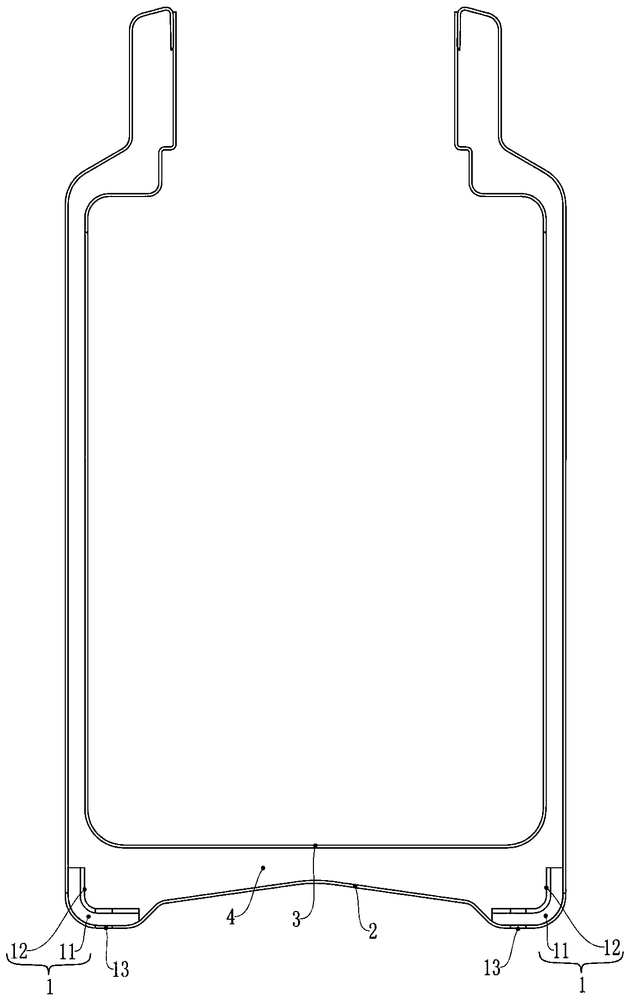
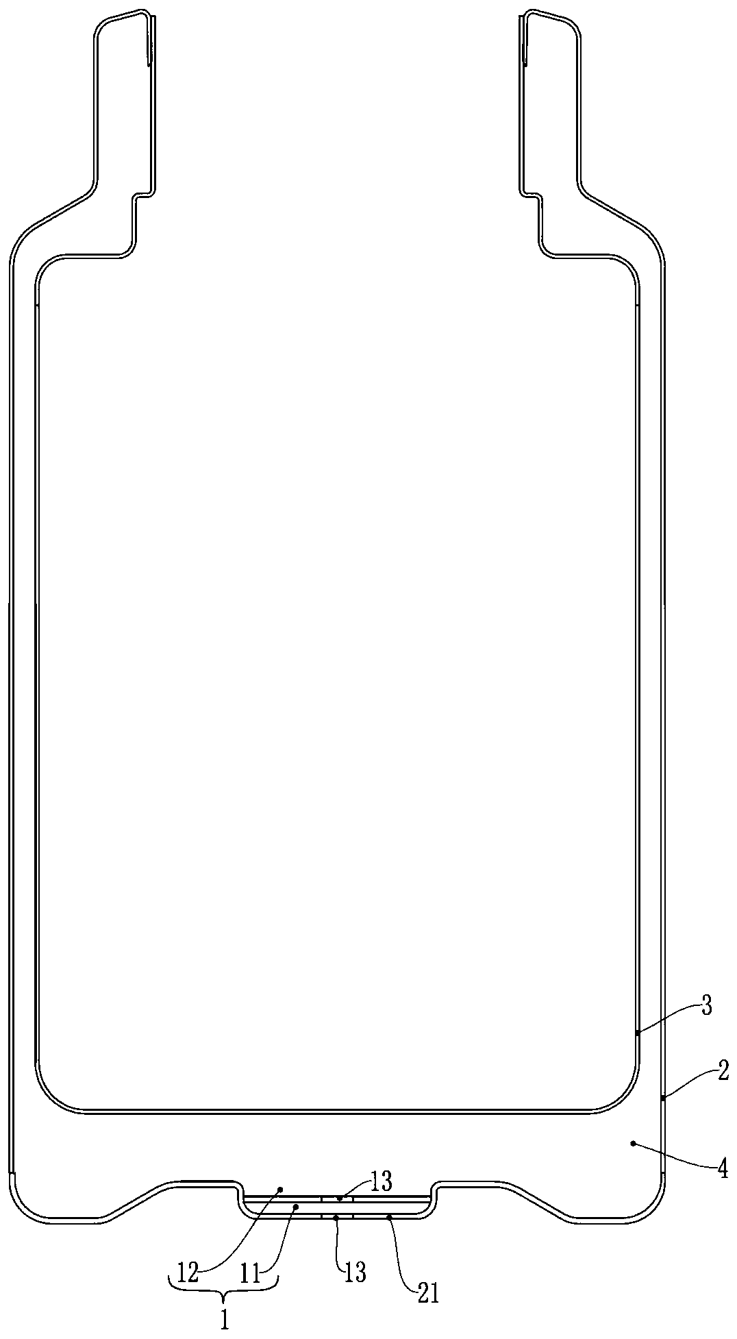
[0055] The good air-tight insulation container preparation method of the present embodiment, as figure 1 As shown, the heat preservation container is a heat preservation container formed by vacuumizing between the outer shell 2 and the inner shell 3 made of metal, and a sealed vacuum heat preservation cavity 4 is formed between the outer shell 2 and the inner shell 3, comprising the following steps :

[0056] Step A, prepare the auxiliary part 1, the auxiliary part 1 is formed by stacking the low-temperature sealing layer 11 and the high-temperature covering layer 12 and welding each other, and the low-temperature sealing layer 11 is made of metal that will melt at the melting temperature, so The high-temperature covering layer 12 is made of a metal that does not melt at the melting temperature;

...


PUM

PropertyMeasurementUnit
melting pointaaaaaaaaaa

Abstract

An insulated container and a preparation method therefor. The insulated container is formed by vacuuming the space between an outer shell (2) and an inner shell (3) that are made of metal; an auxiliary member (1) is fixed at a corner of the inner side of the outer shell (2); the auxiliary member (1) is formed by stacking and welding a low temperature sealing layer (11) and a high temperature covering layer (12); the low temperature sealing layer (11) is made of a metal which melts at a melting temperature, and the high temperature covering layer (12) is made of a metal that does not melt at the melting temperature; the low temperature sealing layer (11) is fixed between the high temperature coating layer (12) and the outer shell (2); a vent hole (13) is drilled through the auxiliary member (1) and the outer shell (2). The insulted container is placed in a vacuuming chamber; the temperature of the vacuuming chamber is gradually increased to the melting temperature while vacuumizing, and the low temperature sealing layer (11) is melted by heat and flows until the vent hole (13) is sealed.

Description

technical field [0001] The invention relates to the field of vacuum thermal insulation containers, in particular to a method for preparing a thermal insulation container with good airtightness and the thermal insulation container prepared therefrom. Background technique [0002] The existing tailless vacuum insulation container manufacturing method is to use glass glue to seal the cavity outside the container body at the bottom of the container body. However, because the container body is made of metal, and glass glue is a non-metallic material, glass glue and glass glue are non-metallic materials. The degree of fusion and adhesion of the main body of the container is not good, and the glass glue is easy to crack due to high temperature or vibration. The service life of the insulated container is greatly shortened. If the glass glue is replaced by a low-temperature metal material, the low-temperature metal material is easily oxidized during vacuum heating to generate cracks...

Claims


Application Information

Patent Timeline
Patent Type & Authority Patents(China)
IPC IPC(8): B65D81/38
CPCB65D81/3841
Inventor 刘敏业
Owner FOSHAN KEITH TITANIUM TECH CO LTD
Learn More