Non-core surface coiling method and device

A technology of core roll and mandrel, applied in the field of coiling equipment, can solve problems such as wrinkling and wrinkles, difficulty in coiling flexible materials, slipping, etc., to ensure surface coiling tightness, high coiling efficiency, and simplify machinery structure effect

Pending Publication Date: 2018-06-29
福建富易天龙智能科技有限公司
View PDF12 Cites 1 Cited by
  • Summary
  • Abstract
  • Description
  • Claims
  • Application Information

AI Technical Summary

Problems solved by technology

However, there is no core in coreless surface winding, and it is very difficult to roll up flexible materials. Even if it can be rolled up sometimes, problems such as slipping, wrinkling and wrinkles are prone to occur when rolling up.

Method used


Image

  • Non-core surface coiling method and device
  • Non-core surface coiling method and device

Examples


Embodiment 1

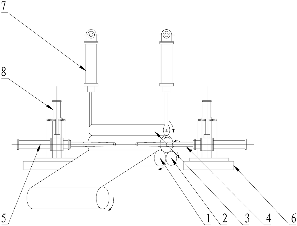
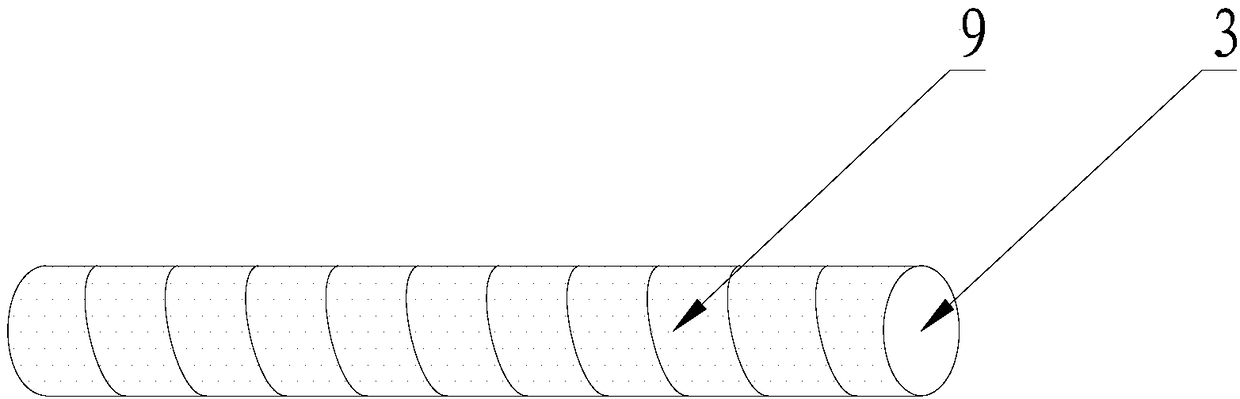
[0048] Please refer to figure 1 as well as figure 2 , Embodiment 1 of the present invention is: a coreless surface coiling device, including a rear support roller 1, a front support roller 2, a pressing roller 3, a pressing roller cylinder 7 and symmetrically arranged at the end of the pressing roller 3 Mandrel 4, mandrel cylinder 5 and mandrel lifting cylinder 8 on both sides;

[0049] The axes of the back support roll 1, the front support roll 2, the press roll 3 and the mandrel 4 are parallel to each other, the turning and linear speed of the back support roll 1 and the front support roll 2 are the same, and the back support roll 1 and the There is a gap between the front support rollers 2, the pressing roller 3 is located above the gap, the top height of the front support roller 2 is lower than the top height of the rear support roller 1, and the mandrel cylinder 5 is located On the axis where the mandrel 4 is located, the piston rod of the mandrel cylinder 5 is connect...

Embodiment 2

[0050] Please refer to figure 1 as well as figure 2 , the second embodiment of the present invention is: a coreless surface coiling device, including a rear support roll 1, a front support roll 2, a pressing roll 3, a pressing roll cylinder 7 and symmetrically arranged at the end of the pressing roll 3 Mandrel 4, mandrel cylinder 5 and mandrel lifting cylinder 8 on both sides;

[0051] The axes of the back support roll 1, the front support roll 2, the press roll 3 and the mandrel 4 are parallel to each other, the turning and linear speed of the back support roll 1 and the front support roll 2 are the same, and the back support roll 1 and the There is a gap between the front support rollers 2, the pressing roller 3 is located above the gap, the top height of the front support roller 2 is lower than the top height of the rear support roller 1, and the mandrel cylinder 5 is located On the axis where the mandrel 4 is located, the piston rod of the mandrel cylinder 5 is connecte...


PUM


Abstract

The invention relates to the technical field of coiling devices, in particular to a non-core surface coiling method and device. The non-core surface coiling method is used for coiling a base materialinto a non-core coiled material. The base material is placed on two roller bodies, wherein the axes of the two roller bodies are parallel, and the steering directions of the two roller bodies are thesame. Core shafts are pressed and attached to the positions between the two roller bodies through a pressing roller, the base material is wound around the surface of the core shaft through friction force between the roller bodies and the core shafts, the core shafts are drawn out along the axis after the base material is coiled, and the base material is gradually coiled into the non-core coiled material. The non-core surface coiling device comprises a rear supporting roller, a front supporting roller, the pressing roller, a pressing roller air cylinder, the core shafts symmetrically arranged on the two ends of the end portion of the pressing roller, core shaft air cylinders and core shaft lifting air cylinders. By means of the non-core surface coiling method and device, the structure is simple, implementation is easy, the coiling efficiency is high, the effect is good, the beneficial effects that the coiling rate is 100%, the coiling rate is adjustable, and the coiling end face is flatare achieved, and the method and device are suitable for full-automatic non-core surface coiling work of flexible materials.

Description

technical field [0001] The invention relates to the technical field of coiling equipment, in particular to a method and device for coreless surface coiling. Background technique [0002] In the surface winding process of flexible materials (such as cloth, gauze, paper, film, carpet, etc.), according to the two different needs of users for cored rolls and coreless rolls, there are two surface winding technologies, that is, cored rolls. There are two technologies of surface coiling and coreless surface coiling. The cored surface winding has a winding core, which can realize reliable winding through the winding core and the corresponding surface winding mechanism. However, there is no core in coreless surface winding, and it is very difficult to roll flexible materials. Even if rolling can be achieved sometimes, problems such as slipping, wrinkling and wrinkles are prone to occur during rolling. Therefore, the present invention provides a method and device for coreless surfac...

Claims


Application Information

Patent Timeline
Patent Type & Authority Applications(China)
IPC IPC(8): B65H23/16B65H23/26B65H23/195B65H18/08
CPCB65H18/08B65H23/16B65H23/1955B65H23/26B65H2701/19
Inventor 林学龙韦习成
Owner 福建富易天龙智能科技有限公司
Why Eureka
Try Eureka