Flush powered slide door handle with self-centering bell crank

A sliding door and handle technology, applied in the field of pivoting handles, can solve problems such as difficulty in grasping and pulling

Active Publication Date: 2018-06-29
TOYOTA JIDOSHA KK
View PDF5 Cites 4 Cited by
  • Summary
  • Abstract
  • Description
  • Claims
  • Application Information

AI Technical Summary

Problems solved by technology

The manual "grab" style handles commonly used on most vehicles are not necessarily operable without a relatively strong grip and pull, which can be difficult if the person's hands are not free

Method used


Image

  • Flush powered slide door handle with self-centering bell crank
  • Flush powered slide door handle with self-centering bell crank
  • Flush powered slide door handle with self-centering bell crank

Examples


Embodiment Construction

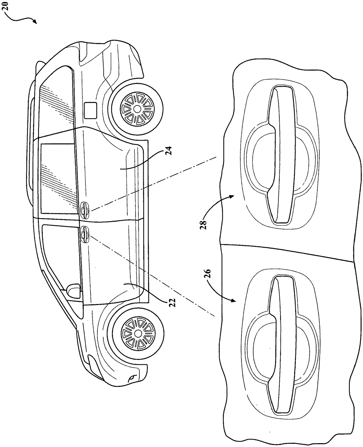
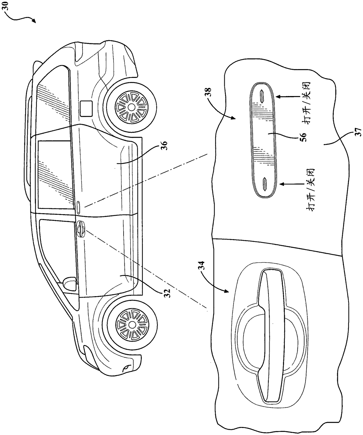
[0034] The technology generally relates to minivan sliding door handle assemblies and exteriors. In particular, the handle assembly is provided with an outer surface that is substantially flush with the outer panel or outer surface of the power sliding door. The handle assembly is preferably operated in power mode, however it maintains manual opening / closing operation of the sliding door when necessary. For example, sliding doors are intended to be operated primarily in a power mode, actuated by lightly depressing one of the two opposing ends of the pivoting handle to actuate an internal switch, thereby providing a power open / close function. However, in the event of an emergency or loss of vehicle power, the handle assembly is designed to otherwise maintain a manual mode of operation. To operate the manual mode, the user presses one of the two opposite ends further an additional distance, which releases the locking mechanism, exposing the other of the two ends of the pivoting...


PUM


Abstract

A self-centering handle assembly is provided for a vehicle door. The handle assembly includes a pivoting handle base coupled to the vehicle door at a pivot axis, and includes a front face having a first and second opposing ends. The first and seconds ends are configured for a selective pivotal movement in opposite directions about the pivot axis. First and second drive arms are provided extendinga distance from a rear portion of the handle base and configured for coordinated movement with the respective first and second ends of the handle base. A bell crank is provided, coupled to the handleassembly, and configured to rotate about a second pivot axis. Rotation of the bell crank is driven by movement of the first and second drive arms. A biasing member is in contact with the bell crank and urges the bell crank to a return to a self-centering, rest position.

Description

[0001] Cross References to Related Applications [0002] This application claims the benefit of US Provisional Application No. 62 / 431,996, filed December 9, 2016, which is incorporated by reference in its entirety. technical field [0003] The present disclosure relates generally to a flush handle for a door or other closure, and more particularly to a pivot handle configured to open a sliding door of a vehicle in both a power mode and a manual mode . Background technique [0004] The background description provided in this specification is for the purpose of generally presenting the context of the disclosure. The work of the presently named inventors (to the extent that can be described in this Background section), and aspects of the description that may not be prior art at the time of filing, are neither expressly nor implicitly admitted as part of the present invention. technology prior art. [0005] Minivan-type vehicles typically have a pair of pivoting front passeng...

Claims


Application Information

Patent Timeline
Patent Type & Authority Applications(China)
IPC IPC(8): E05B85/14E05B79/22
CPCE05B79/22E05B83/40E05B85/103E05B85/16E05B77/04E05B77/14E05B85/00E05B85/10E05B85/14E05B77/12E05B81/76Y10S292/31E05B2001/0076Y10T292/57E05F15/79B60J5/06E05B79/06E05B79/16E05B77/06
Inventor T·顺通维纳特石川善基F·A·理查兹岩间贵弘铃木秀人
Owner TOYOTA JIDOSHA KK
Why Eureka
Try Eureka