Lifting mechanism

A technology of lifting mechanism and gear row, which is applied in the direction of mechanical equipment, portable lifting device, friction transmission device, etc., can solve the problems of automatic change of meshing force, large space occupied by the mechanism, low reliability, etc., and achieve the protection of system components, Space saving, simple and reliable structure

Active Publication Date: 2018-06-29
睿恩光电有限责任公司
View PDF9 Cites 0 Cited by
  • Summary
  • Abstract
  • Description
  • Claims
  • Application Information

AI Technical Summary

Problems solved by technology

[0004] In order to solve the problems of complex parts, high cost, large space occupied by the mechanism, low reliability or inability to automatically change the meshing force within a specific range of motion in the prior art gearbox or pressed shrapnel, the present invention proposes a lifting mechanism. Through the combination of a single special flexible cantilever tooth row and gears, the meshing force can be automatically changed

Method used


Image

  • Lifting mechanism
  • Lifting mechanism
  • Lifting mechanism

Examples


specific Embodiment 1

[0033] A lifting mechanism of the present invention, a lifting mechanism, includes a flexible cantilever gear row 1 and a gear set 2, the flexible cantilever gear row 1 is a flexible material, and includes a fixed end 101 and a gear row end 102; The teeth of the gear row end 102 are in interference fit with the gear set 2; the gear set is 1 gear or N+1 gear.

[0034] Further, the fixed end 101 includes a fixing hole 1011 and a positioning hole 1012, the fixing hole 1011 is fixedly connected to the mechanism through a fixing pin, and the positioning hole 1012 is connected to the mechanism through a positioning pin with a loose fit tolerance.

[0035] Further, the fixing holes 1011 and the positioning holes 1012 are on non-overlapping axes.

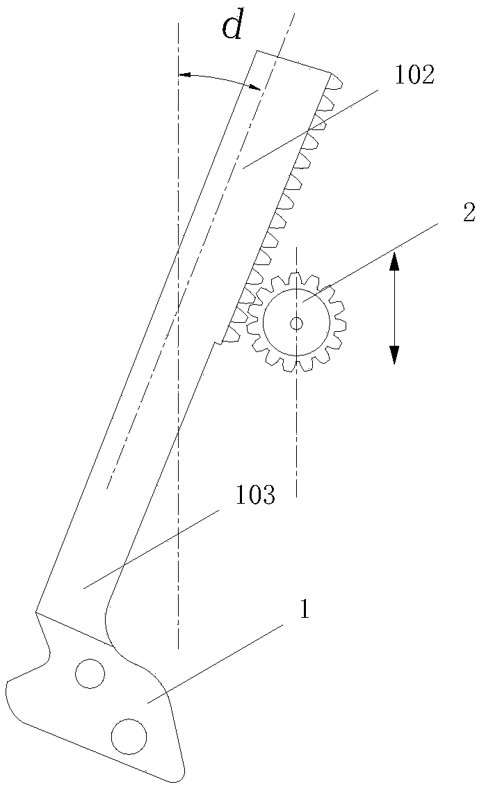
[0036] Further, the flexible cantilever tooth row 1 is provided with an offset angle on the axis, and the included angle is an acute angle; the gear set 2 is a gear, and the gear is aligned with the tooth row when moving in the vertical dir...

specific Embodiment 2

[0039] A lifting mechanism of the present invention, a lifting mechanism, includes a flexible cantilever gear row 1 and a gear set 2, the flexible cantilever gear row 1 is a flexible material, and includes a fixed end 101 and a gear row end 102; The teeth of the gear row end 102 are in interference fit with the gear set 2; the gear set is 1 gear or N+1 gear.

[0040] Further, the fixed end 101 includes a fixing hole 1011 and a positioning hole 1012, the fixing hole 1011 is fixedly connected to the mechanism through a fixing pin, and the positioning hole 1012 is connected to the mechanism through a positioning pin with a loose fit tolerance.

[0041] Further, the fixing holes 1011 and the positioning holes 1012 are on non-overlapping axes.

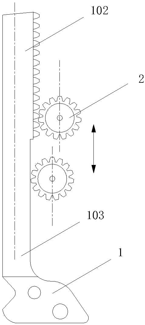
[0042] Further, the axis of the flexible cantilever tooth row 1 is perpendicular to the horizontal plane; the gear set 2 is two gears, the positioning holes of the two gears are on the non-overlapping axis, and the gear set is in the vertic...

specific Embodiment 3

[0045] A lifting mechanism of the present invention, a lifting mechanism, includes a flexible cantilever gear row 1 and a gear set 2, the flexible cantilever gear row 1 is a flexible material, and includes a fixed end 101 and a gear row end 102; The teeth of the gear row end 102 are in interference fit with the gear set 2; the gear set is 1 gear or N+1 gear.

[0046] Further, the fixed end 101 includes a fixing hole 1011 and a positioning hole 1012, the fixing hole 1011 is fixedly connected to the mechanism through a fixing pin, and the positioning hole 1012 is connected to the mechanism through a positioning pin with a loose fit tolerance.

[0047] Further, the fixing holes 1011 and the positioning holes 1012 are on non-overlapping axes.

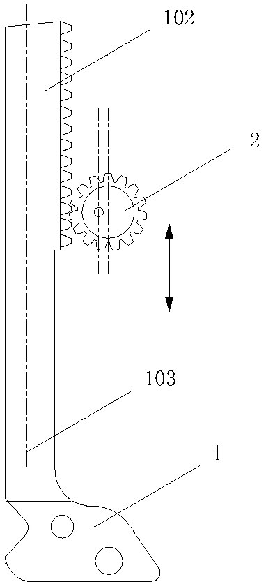
[0048] Further, the axis of the flexible cantilever tooth row 1 is perpendicular to the horizontal plane; the gear set 2 is a gear, the gear is an eccentric gear, and the number of teeth of the eccentric gear matches the number of teeth of ...


PUM


Abstract

The invention provides a lifting mechanism. By adoption of the lifting mechanism, the problems of complex parts, high cost, large space occupation of mechanisms, poor reliability or unavailable automatic changes of engaging force within a certain movement range of gearboxes or pressing elastic pieces in the prior art are solved. According to the lifting mechanism, a single special flexible cantilever gear rack and gears are combined to automatically change the engaging force. The lifting mechanism comprises a flexible cantilever gear rack and a gear set. The flexible cantilever gear rack is made of flexible materials and comprises a fixed end and a gear rack end. Gear rack teeth at the gear rack end are in interference fit with the gear set. The gear set comprises one or N+1 gears. According to the lifting mechanism, as the engaging force can be changed, the purpose of adjusting the front-back moving speed can be achieved, and a gear positioning effect can also be achieved; and meanwhile, the lifting mechanism is safe, capable of preventing collision and suitable for a mechanical driving system which is simple and reliable in structure and has no redundant accommodating space.

Description

technical field [0001] The invention relates to a lifting mechanism, which realizes the function change of the lifting movement through the change of the meshing force generated by the interactive movement of the flexible cantilever tooth row and the gear, and particularly relates to a flexible cantilever tooth row and gear structure with variable meshing force lifting mechanism. Background technique [0002] In the prior art, in order to adjust the meshing force to realize the step-shift function, the technical methods usually adopted include gear box or pressing shrapnel. However, the components of the gear box structure are complicated and costly, and the reliability and durability are limited; although the pressing shrapnel can also change the meshing force, it cannot automatically change the meshing force within a specific range of motion. In the prior art, in order to realize the end point positioning function, the technical methods usually adopted include slots or re...

Claims


Application Information

Patent Timeline
Patent Type & Authority Applications(China)
IPC IPC(8): F16H19/04F16H55/28F16H55/06
CPCF16H19/04F16H55/06F16H55/28
Inventor 李其儒余林涛黄鸿立
Owner 睿恩光电有限责任公司
Why Eureka
Try Eureka