
Display panel and display device

A technology of display panel and display area, applied in static indicators, static memory, instruments, etc., can solve the problems of scanning signal attenuation, uneven display, etc., and achieve the effect of improving uniformity, simple circuit design, and improving display effect.

Active Publication Date: 2018-06-29
XIAMEN TIANMA MICRO ELECTRONICS
View PDF5 Cites 10 Cited by
  • Summary
  • Abstract
  • Description
  • Claims
  • Application Information

AI Technical Summary

Problems solved by technology

[0004] The present invention provides a display panel and a display device to solve the problem of uneven display caused by the attenuation of the scanning signal on the scanning line, improve the uniformity of display, and improve the display effect

Method used


Image

  • Display panel and display device
  • Display panel and display device
  • Display panel and display device

Examples


Embodiment Construction

[0020] The present invention will be further described in detail below in conjunction with the accompanying drawings and embodiments. It should be understood that the specific embodiments described here are only used to explain the present invention, but not to limit the present invention. In addition, it should be noted that, for the convenience of description, only some structures related to the present invention are shown in the drawings but not all structures.

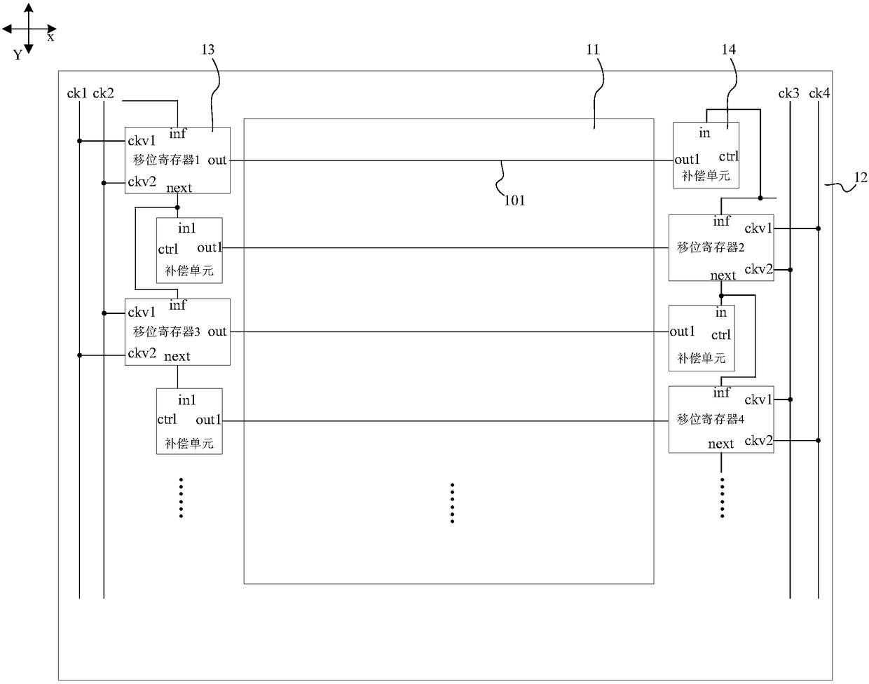
[0021] figure 1 is a schematic structural diagram of a display panel provided by an embodiment of the present invention, refer to figure 1 , the display panel includes:

[0022] A plurality of scanning lines 101 arranged along the first direction Y and extending along the second direction X, the plurality of scanning lines 101 are located in the display area 11; wherein, the first direction Y and the second direction Y intersect, and the first direction Y and the second direction X The direction X may be vertica...


PUM


Abstract

The invention discloses a display panel and a display device, wherein the display panel comprises a plurality of scanning lines, a multi-level shifting register, a plurality of compensation units, wherein the plurality of scanning lines are arranged along a first direction and extend along a second direction, and are positioned in a display area; a starting signal input end of a (M+2)th-level shifting register is connected with a first output end of a Mth-level shifting register, a second output end of each-level shifting register is connected with one corresponding scanning line; the plurality of compensation units are positioned on a peripheral circuit area; a control end of each compensation unit is used for inputting a clock signal, and an output end is connected with a corresponding scanning line which is connected with one shifting register; an input end is connected with a corresponding first output end of a first N-level shifting register of the shifting register, and is used for compensating signals on the scanning lines according to the control end and input end thereof, wherein M and N are positive integer. According to the technical scheme provided by the embodiment ofthe invention, the scanning signal on the scanning lines can be compensated, display uniformity can be improved, the border of the display panel is small.

Description

technical field [0001] Embodiments of the present invention relate to the field of display technology, and in particular, to a display panel and a display device. Background technique [0002] In the display process of the existing display panel, the shift register located in the non-display area generally outputs the scan signal to the scan line, and the scan signal on the scan line drives the pixels in the connected display area to charge and display. [0003] In the interlace driving method of double-sided driving, the scan signal output by the shift register circuit attenuates at the end of the scan line, especially in the case of a large panel with heavy resistance and capacitance load RC loading, the scan signal The attenuation is more serious, which will cause insufficient opening of the transistors in the pixels connected to the end of the scanning line, low pixel charging efficiency, resulting in inconsistent brightness between the edge and the middle area of ​​the ...

Claims


Application Information

Patent Timeline
Patent Type & Authority Applications(China)
IPC IPC(8): G09G3/20G11C19/28
CPCG09G3/20G11C19/28G09G2310/0286
Inventor 郑志伟杨康鹏许育民
Owner XIAMEN TIANMA MICRO ELECTRONICS
Learn More