
Display device, device and display control method

A display control method and display device technology, which are applied in semiconductor/solid-state device manufacturing, lighting devices, static indicators, etc., can solve the problem of high cost of double-sided display devices and achieve the effect of low production cost

Active Publication Date: 2020-06-30
BOE TECH GRP CO LTD
View PDF6 Cites 0 Cited by
  • Summary
  • Abstract
  • Description
  • Claims
  • Application Information

AI Technical Summary

Problems solved by technology

[0004] The purpose of the present invention is to at least solve one of the above-mentioned technical defects, especially the problem that the image of the double-sided display device is a mirror image and the problem that the cost of the double-sided display device is normally displayed.

Method used


Image

  • Display device, device and display control method
  • Display device, device and display control method
  • Display device, device and display control method

Examples


Embodiment 1

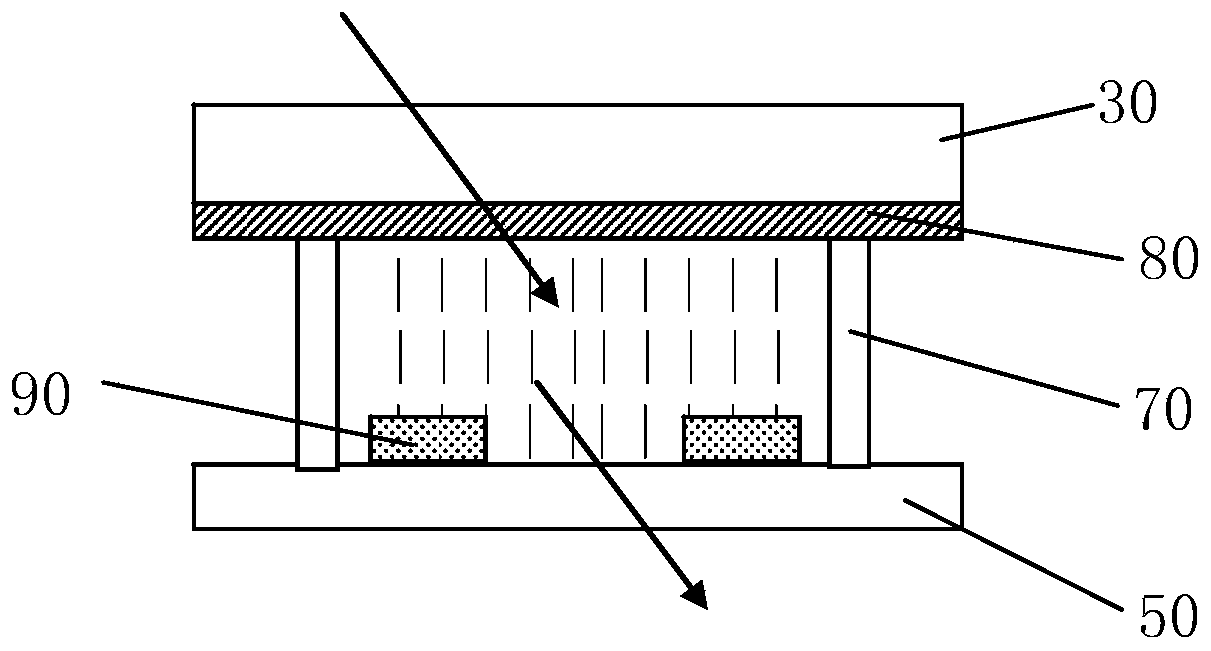
[0067] A display control method, characterized in that, using the display device, the first dimming layer / second dimming layer of each display device are located on the same side of the display device, and the control method includes: S110 To S120.

[0068] S110: Apply the same signal to the light-emitting layers in the two display devices associated according to a preset rule in each row.

[0069] As mentioned above, the display device includes a plurality of display devices arranged in a matrix. In the display device, the light-emitting layer 30 is a pixel unit, and the pixel unit includes one or more sub-pixel units. When the display device displays on both sides, in order to make the display device display normally, the problem of mirroring does not occur, so the two corresponding display devices in each row receive the same signal, and the corresponding two display devices are set according to the preset rules For the display device capable of applying the same electrical sig...

Embodiment 2

[0083] A display control method, applying the display device, the first dimming layer / second dimming layer of each display device are located on the same side of the display device, and the control method includes:

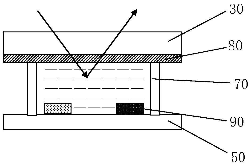
[0084] S140: Control the first dimming layer of each of the display devices in each row to be in a reflective state, and control the second dimming layer of each of the display devices in each row to be in a transmissive state to realize single-sided display .

[0085] In the embodiment of the present invention, the first dimming layer 20 / second dimming layer 40 of each display device are located on the same side of the display device, that is, the first dimming layer of each display device Layer 20 / second dimming layer 40 are all located on one side of the display device. For example, the display device includes a first side and a second side corresponding to the first side. The light layer is the first dimming layer 20, and the corresponding dimming layer of all dis...


PUM


Abstract

The present invention provides a display device, comprising: a first substrate, a first light-adjusting layer, a light-emitting layer, a second light-adjusting layer, and a second substrate stacked in sequence, and both the first light-adjusting layer and the second light-adjusting layer are used To control the light incident therein to switch between reflection and transmission; the first light-adjusting layer is used to control the light emitted by the light-emitting layer and incident on the first light-adjusting layer to reflect and not pass through the first light-adjusting layer Or transmit and emit from the side where the first substrate is located; the second light-adjusting layer is used to control the light emitted by the light-emitting layer and incident on the second light-adjusting layer to reflect and not pass through the second light-adjusting layer Or transmit and emit from the side where the second substrate is located. Applying the display device of the present invention in combination with the display control method avoids that the images on both sides of the display device are in a mirror image relationship during display, and the two-sided display device can display images normally, and at the same time, the double-sided display device can be switched to single-sided display, so as to save energy consumption and economic cost.

Description

Technical field [0001] The present invention relates to the field of optoelectronic technology and display device manufacturing. Specifically, the present invention relates to a display device, a device and a display control method. Background technique [0002] With the development of display technology, people usually need double-sided display devices capable of displaying images on both sides of the display. This double-sided display device is used in business halls in the communications industry, government windows, financial industries, transportation industries, and window industries, such as airports, railway stations, subway stations, canteens and other public places with high traffic. Therefore, double The surface display device has broad application prospects. [0003] At present, common OLED double-sided display devices use thinner metal electrodes and semi-transparent materials to realize simultaneous display of the front and back sides of the display device. However, ...

Claims


Application Information

Patent Timeline
Patent Type & Authority Patents(China)
IPC IPC(8): H01L27/32H01L51/52H05B44/00
CPCH10K59/12H10K50/85H10K2102/3031H10K59/50H10K59/128H10K2102/3023G09G2300/023G09G2300/026G09G3/3433
Inventor 孙海雁苗浩李锐朱红张鹏举刘明星
Owner BOE TECH GRP CO LTD
Learn More