
Terminal inserting machine

A technology of insertion machine and terminal, which is applied in the assembly/disassembly of contacts, etc., can solve the problems of difficult automatic insertion, high error rate of manual insertion, and waste, so as to save manpower and material resources, avoid error-prone, and scrap rate Reduced effect

Pending Publication Date: 2018-06-29
昆山沪光汽车电器股份有限公司
View PDF0 Cites 2 Cited by
  • Summary
  • Abstract
  • Description
  • Claims
  • Application Information

AI Technical Summary

Problems solved by technology

When the wires are stored and transferred between different stations, the wires will be deformed, which brings difficulties for automatic insertion. It can only rely on manual insertion, which requires a lot of manpower, and the error rate of manual insertion is high, and the output A large number of defective products, resulting in a lot of waste

Method used


Image

  • Terminal inserting machine
  • Terminal inserting machine
  • Terminal inserting machine

Examples


Embodiment Construction

[0017] In order to further describe the technical features and effects of the present invention, the present invention will be further described below in conjunction with the accompanying drawings and specific embodiments.

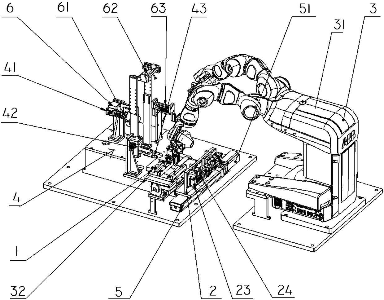
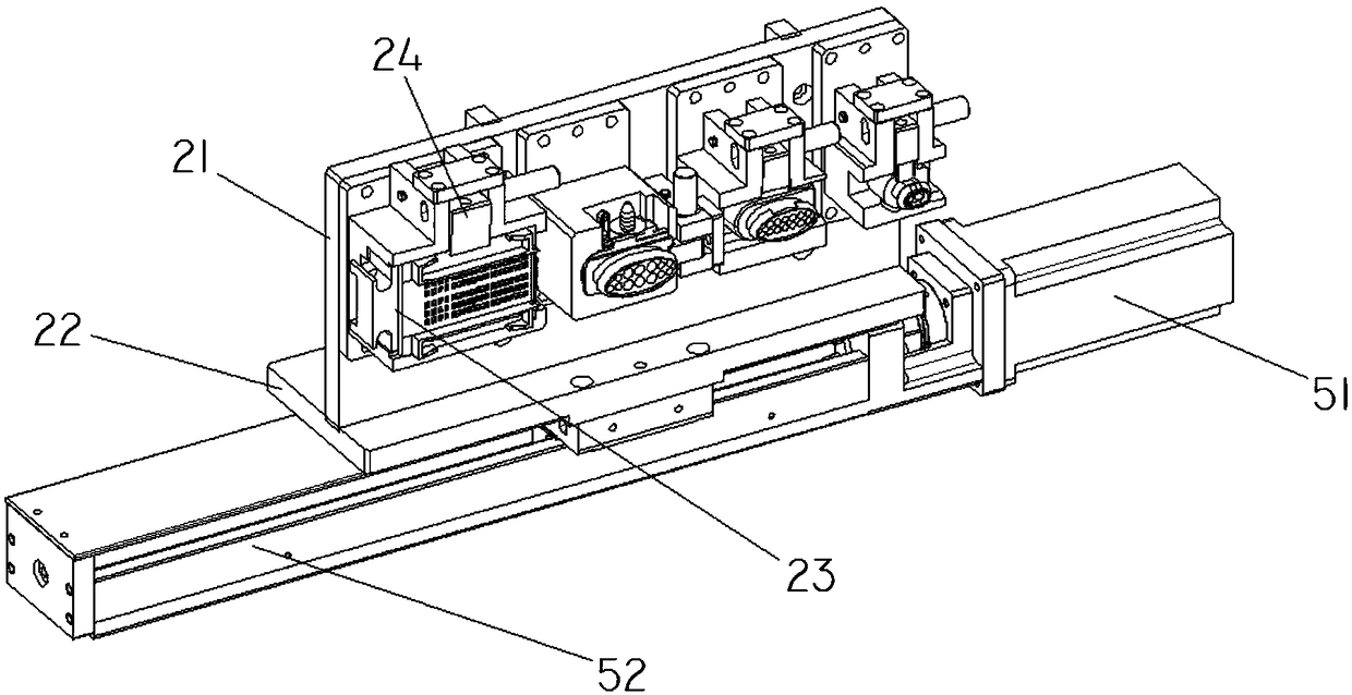
[0018] refer to Figure 1-Figure 4 , a terminal insertion machine, including a clamping device 3, a wire fixing device 1, a sheath fixing device 2, a camera system 4, a linear motion module 5, and a lighting system 6; the wire fixing device 1 is arranged on a tooling plate 7 Above, the sheath fixing device 2 is set on the linear motion module 5, the linear motion module 5 is set next to the wire fixing device 1, the camera system 4 and the lighting system 6 are both set on the tooling plate 7, located on the wire fixing device 1 Next to it, the clamping device 3 is arranged beside the tooling plate 7 .

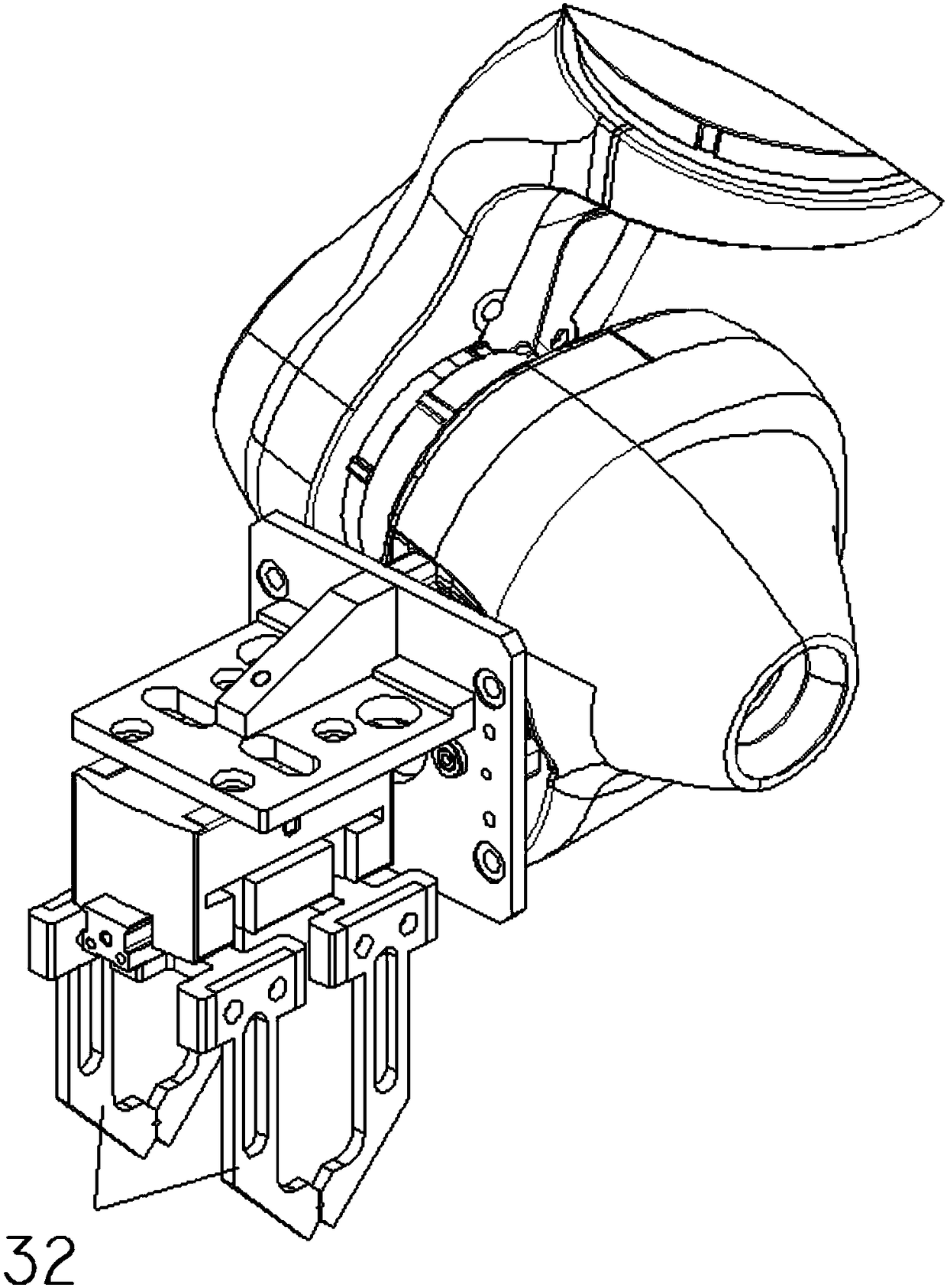
[0019] Further, the clamping device 3 includes a mechanical arm 31 , and two clamping jaws 32 are arranged at the end of the mechanical arm 31 .

[0020...


PUM


Abstract

The invention discloses a terminal inserting machine which comprises a clamping device, a lead fixing device, a jacket fixing device, a camera system, a linear motion module and a lighting system. Thelead fixing device is arranged on a tooling plate, the jacket fixing device is arranged on the linear motion module which is arranged beside the lead fixing device, both the camera system and the lighting system are arranged on the tooling plate and positioned beside the lead fixing device, and the clamping device is arranged beside the tooling plate. The terminal inserting machine can guaranteeautomatic inserting of a lead terminal and can ensure the terminal to be inserted into a jacket accurately, so that proneness to errors if inserting is performed manually are avoided, repeatability ishigh, rejection rate is reduced, and a lot of manpower and material resources are saved.

Description

technical field [0001] The invention belongs to the technical field of wire harness processing and assembly, and in particular relates to a terminal insertion machine. Background technique [0002] In the prior art, it is necessary to manually insert the terminal of a single wire into the connector sheath. When the wires are stored and transferred between different stations, the wires will be deformed, which brings difficulties for automatic insertion. It can only rely on manual insertion, which requires a lot of manpower, and the error rate of manual insertion is high, and the output A large number of defective products cause a lot of waste. Contents of the invention [0003] In order to solve the above problems, the present invention provides a terminal insertion machine, which can realize automatic insertion of wires. [0004] The technical problem to be solved by the present invention is achieved through the following technical solutions: [0005] A terminal inserti...

Claims


Application Information

Patent Timeline
IPC IPC(8): H01R43/20
CPCH01R43/20
Inventor 成三荣周晔
Owner 昆山沪光汽车电器股份有限公司
Learn More