Kafka-based monitoring method, device and system
A technology for monitoring objects and monitoring terminals, applied in the computer field, can solve the problems of inability to monitor, high cost, and inability to aggregate monitoring results, and achieve the effect of reducing costs
- Summary
- Abstract
- Description
- Claims
- Application Information
AI Technical Summary
Problems solved by technology
Method used
Image

Examples
Embodiment 1
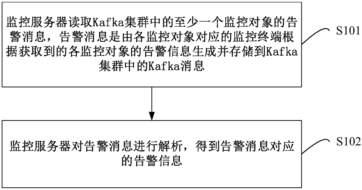
[0042] figure 1It is a flow chart of the Kafka-based monitoring method provided by Embodiment 1 of the present invention. The embodiments of the present invention aim at realizing comprehensive monitoring of large-scale application systems in the prior art, requiring the installation of multiple monitoring tools of different versions, which cannot summarize the monitoring results of each monitored device, which affects the monitoring effect, and the cost of realizing monitoring For Gao's question, a Kafka-based monitoring method is provided. Such as figure 1 , the specific steps of the method are as follows:
[0043] Step S101, the monitoring server reads the alarm message of at least one monitoring object in the Kafka cluster, and the alarm message is a Kafka message generated by the monitoring terminal corresponding to each monitoring object according to the obtained alarm information of each monitoring object and stored in the Kafka cluster .
[0044] In this embodiment...
Embodiment 2
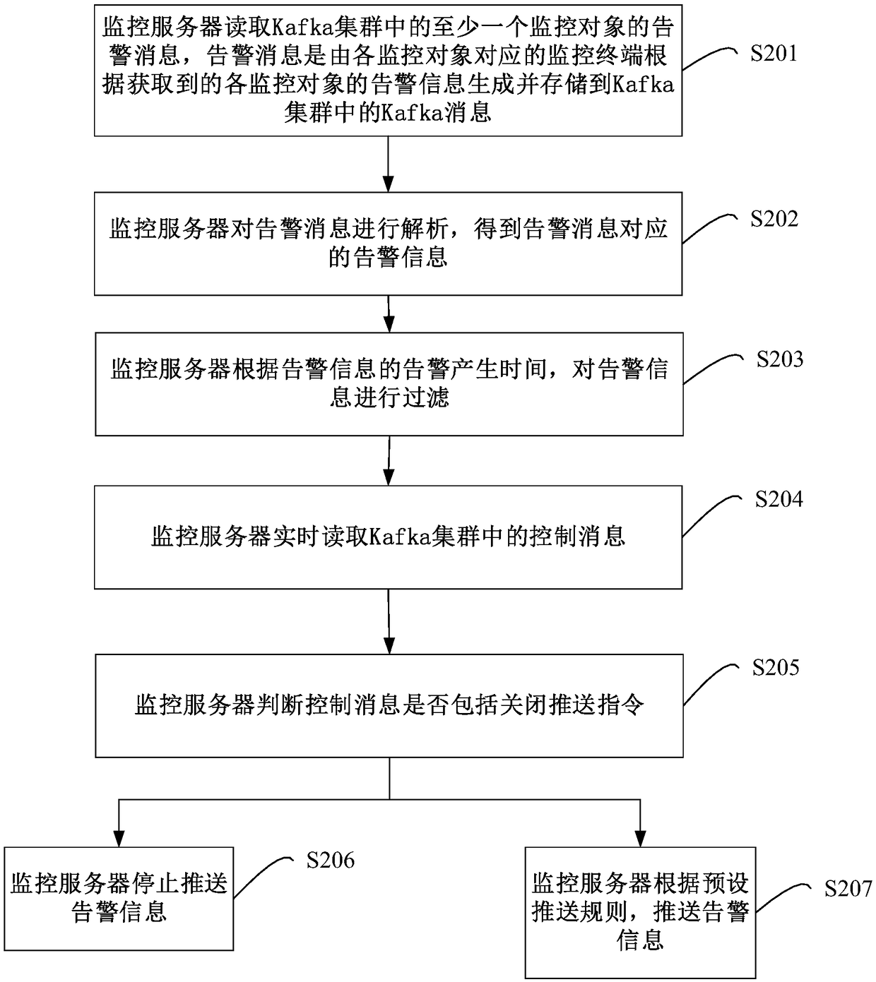
[0054] figure 2 It is a flow chart of the Kafka-based monitoring method provided by Embodiment 2 of the present invention. On the basis of the first embodiment above, in this embodiment, after the monitoring server parses the alarm message and obtains the alarm information corresponding to the alarm message, it further includes: the monitoring server pushes the alarm information according to the preset push rule, and the preset The push rule includes at least the information of the person to be pushed and the push method. Such as figure 2 As shown, the specific steps of the method are as follows:
[0055] Step S201, the monitoring server reads the alarm message of at least one monitoring object in the Kafka cluster, and the alarm message is a Kafka message generated by the monitoring terminal corresponding to each monitoring object according to the obtained alarm information of each monitoring object and stored in the Kafka cluster .
[0056] In this embodiment, the moni...
Embodiment 3
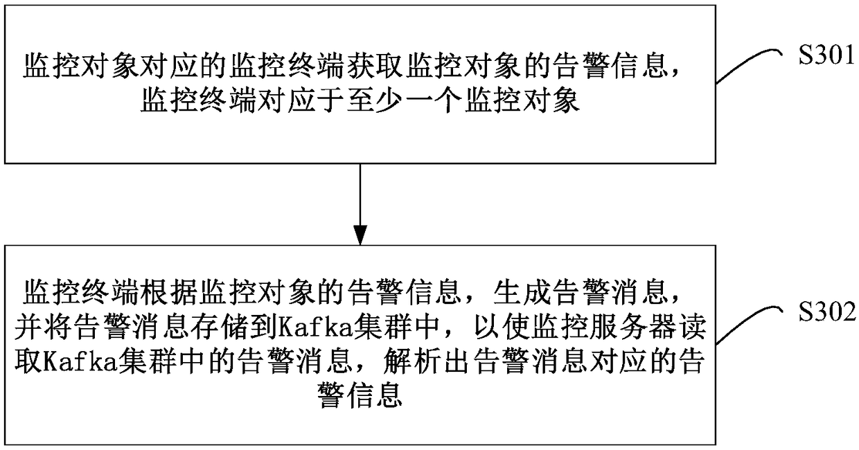
[0089] image 3 It is a flow chart of the Kafka-based monitoring method provided by Embodiment 3 of the present invention. The embodiments of the present invention aim at realizing comprehensive monitoring of large-scale application systems in the prior art, requiring the installation of multiple monitoring tools of different versions, which cannot summarize the monitoring results of each monitored device, which affects the monitoring effect, and the cost of realizing monitoring For Gao's question, a Kafka-based monitoring method is provided. Such as image 3 , the specific steps of the method are as follows:
[0090] Step S301, the monitoring terminal corresponding to the monitoring object obtains the alarm information of the monitoring object, and the monitoring terminal corresponds to at least one monitoring object.
[0091] In this embodiment, the monitoring server is a server end in the distributed monitoring system, and the monitoring server may be a server installed ...
PUM
 Abstract
Description
Claims
Application Information
 - R&D
- Intellectual Property
- Life Sciences
- Materials
- Tech Scout
- Unparalleled Data Quality
- Higher Quality Content
- 60% Fewer Hallucinations
Browse by: Latest US Patents, China's latest patents, Technical Efficacy Thesaurus, Application Domain, Technology Topic, Popular Technical Reports.
© 2025 PatSnap. All rights reserved.Legal|Privacy policy|Modern Slavery Act Transparency Statement|Sitemap|About US| Contact US: help@patsnap.com