Eureka AIR delivers breakthrough ideas for toughest innovation challenges, trusted by R&D personnel around the world.

Guide slot equipment for plastic steel profiles

A technology of guide grooves and profiles, which is applied in the field of guide groove equipment for plastic steel profiles, and can solve the problem that the size and depth of grooves cannot be changed.

Inactive Publication Date: 2018-07-03
TIANJIN SHENGFA IND & TRADE
View PDF2 Cites 0 Cited by
  • Summary
  • Abstract
  • Description
  • Claims
  • Application Information

AI Technical Summary

Problems solved by technology

With the widespread use of plastic steel doors and windows, the PVC profiles used to make plastic steel doors and windows are customarily called plastic steel profiles. Because of some specific requirements, it is necessary to process strip grooves on the surface of plastic steel profiles. The strip groove processing is now used. The flange is set on the mold for plastic steel profile processing, and the groove is directly set on the surface of the profile when the profile is drawn. The limitation of this design is that the size and depth of the groove cannot be changed basically with the mold, and this kind of The molds can only process plastic steel profiles with grooves, and there are limitations in their use

Method used


Image

  • Guide slot equipment for plastic steel profiles
  • Guide slot equipment for plastic steel profiles
  • Guide slot equipment for plastic steel profiles

Examples


Embodiment Construction

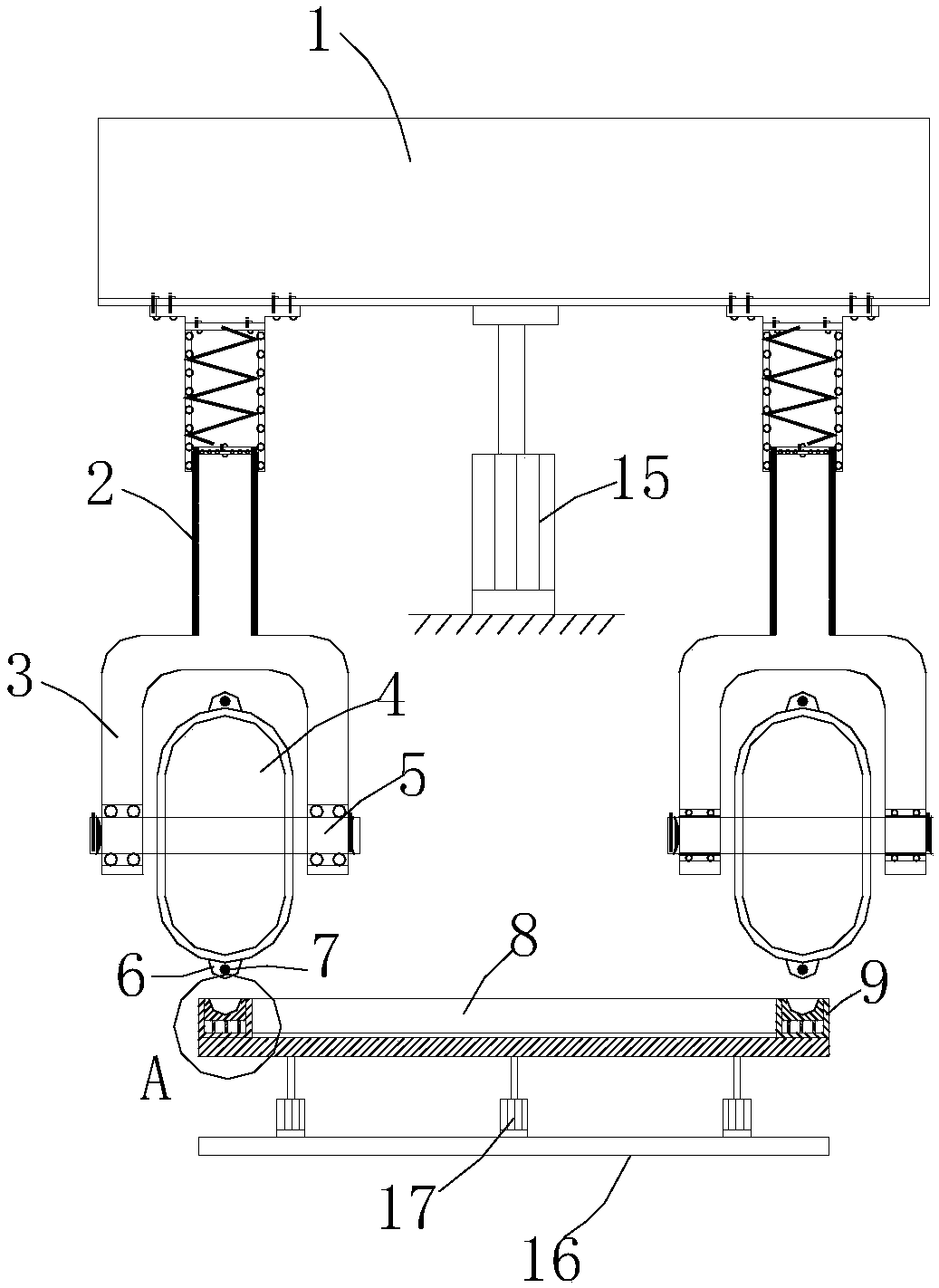
[0014] Such as Figure 1 to Figure 3 As shown, a guide groove device for plastic steel profiles includes a movable connecting plate 1, a support rod 2 is provided at the bottom of the connecting plate 1, and a "U"-shaped splint 3 is provided at the end of the support rod 2, and a "U"-shaped splint 3 is provided. The splint 3 is provided with a rotating pressure wheel 4, which is connected to the "U"-shaped splint 3 through a movable pin shaft 5, and an annular flange 6 is arranged on the peripheral surface of the rotating pressure wheel 4, and an electric heater is embedded in the annular flange 6. Wire 7 is provided with a guide groove mold under the rotating pinch wheel 4;

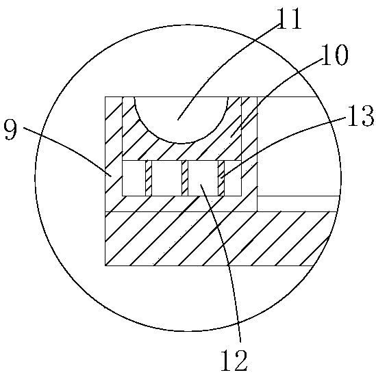
[0015] The guide groove mold comprises a guide groove platform 8, a guide groove plate 9 is provided on both sides of the guide groove platform 8, a placement groove is provided in the guide groove plate 9, a guide groove base 10 is provided in the placement groove, and a guide groove base 10 is provided...


PUM


Abstract

The invention relates to guide slot equipment for plastic steel profiles. The guide slot equipment comprises a movable connecting plate, wherein a supporting rod is arranged at the bottom of the connecting plate; a U-shaped clamping plate is arranged at the end of the supporting rod; a rotary pressure roller is arranged in the U-shaped clamping plate and connected with the U-shaped clamping plateby virtue of a movable pin shaft; annular flanges are arranged on the peripheral surface of the rotary pressure roller; heating wires are inlaid in the annular flanges; a guide slot mold is arranged below the rotary pressure roller and comprises a guide slot platform; guide slot plates are arranged on two sides of the guide slot platform; mounting grooves are formed in the guide slot plates; guideslot bases are arranged in the mounting grooves; concave groove molds are arranged on the guide slot bases; the concave groove molds correspond to the annular flanges on the rotary pressure roller; acooling cavity is formed between the guide slot bases and the bottoms of the mounting grooves; a plurality of supporting plates connected with the guide slot bases are arranged in the cooling cavity;and a plurality of water guide valves communicated with the cooling cavity are arranged at the ends of the guide slot plates. The rotary pressure roller and the guide slot bases can be optionally replaced, and the requirements of grooves with different sizes in the plastic steel profiles are met.

Description

technical field [0001] The invention relates to plastic steel processing equipment, in particular to a guide groove equipment for plastic steel profiles. Background technique [0002] Plastic steel profile refers to the PVC profile used to make doors and windows. Because the doors and windows processed with PVC profiles are not strong enough, steel is usually added to the cavity to enhance the firmness of the doors and windows. Therefore, plastic doors and windows made of steel inside the profile are usually called For plastic steel doors and windows. With the widespread use of plastic steel doors and windows, the PVC profiles used to make plastic steel doors and windows are customarily called plastic steel profiles. Because of some specific requirements, it is necessary to process strip grooves on the surface of plastic steel profiles. The strip groove processing is now used. The flange is set on the mold for plastic steel profile processing, and the groove is directly set...

Claims


Application Information

Patent Timeline
IPC IPC(8): B29C51/18B29C51/42
CPCB29C51/18B29C51/42B29C51/421
Inventor 张法升
Owner TIANJIN SHENGFA IND & TRADE
Why Eureka
Eureka Blog
Learn More