Combination stencil printer and dispenser and related methods

a stencil printer and dispenser technology, applied in the direction of inking apparatus, conductive pattern formation, coating, etc., can solve the problems of reducing the utilization rate of placement systems, and focusing on the more expensive equipment of machines

Active Publication Date: 2012-06-14
ILLINOIS TOOL WORKS INC
View PDF1 Cites 26 Cited by
  • Summary
  • Abstract
  • Description
  • Claims
  • Application Information

AI Technical Summary

Benefits of technology

[0016]Embodiments of the method include imaging fiducials associated with the substrate and aligning the substrate with the stencil when positioning the substrate in the print position. The method further includes delivering the substrate to the substrate support prior to positioning the substrate in the print position, cleaning a bottom surface of the stencil with a cleaning assembly, and / or inspecting the substrate with a vision system to detect a defect with the deposit of viscous material on the substrate. Inspecting the substrate with the vision system includes moving the vision system over the substrate with a vision system gantry under the control of a controller. Depositing viscous material on the substrate with the dispenser is performed after inspecting the substrate with the vision system to detect a defect. The dispenser is configured to fix the defect.
[0017]One more aspect of the disclosure is directed to a combination stencil printer and dispenser including a frame, a stencil coupled to the frame, a substrate support coupled to the frame to support a substrate in a print position, a print head coupled to the frame to deposit and print viscous material over the stencil, and an independent gantry coupled to the frame. The gantry is configured to move in a first direction. The combination stencil printer and dispenser further includes a dispenser coupled to the independent gantry to dispense viscous material on the substrate when the substrate is in the print position.
[0018]Embodiments of the combination stencil printer and dispenser include providing a bracket on a frame member of the independent gantry and a dispensing unit supported by the bracket. The bracket of the dispenser is coupled to a dispenser movement mechanism to move the dispenser with respect to the frame member of the independent gantry in a second direction that is perpendicular to the first direction. The dispenser movement mechanism includes a linear bearing mounted on the frame member of the independent gantry with the bracket being configured to ride along the linear bearing. The dispenser movement mechanism further includes a ball screw coupled to the bracket and configured to drive the movement of the bracket along the linear bearing. The dispenser movement mechanism further includes a motor coupled to the ball screw and configured to drive the rotation of the ball screw. The movement mechanism of the independent gantry includes a pair of rail members secured to the frame and a drive mechanism.

Problems solved by technology

The placement machines are typically the more expensive equipment in the production line, and so effort is made to keep them operating at maximum capacity.
Errors discovered in the printing process may require manual intervention to rectify, which can impact the flow of materials into the placement system, decreasing the utilization of the placement system.

Method used


Image

  • Combination stencil printer and dispenser and related methods
  • Combination stencil printer and dispenser and related methods
  • Combination stencil printer and dispenser and related methods

Examples


Embodiment Construction

[0033]This disclosure is not limited in its application to the details of construction and the arrangement of components set forth in the following description or illustrated in the drawings. The disclosure is capable of other embodiments and of being practiced or of being carried out in various ways. Also, the phraseology and terminology used herein is for the purpose of description and should not be regarded as limiting. The use of “including,”“comprising,”“having,”“containing,”“involving,” and variations thereof herein, is meant to encompass the items listed thereafter and equivalents thereof as well as additional items.

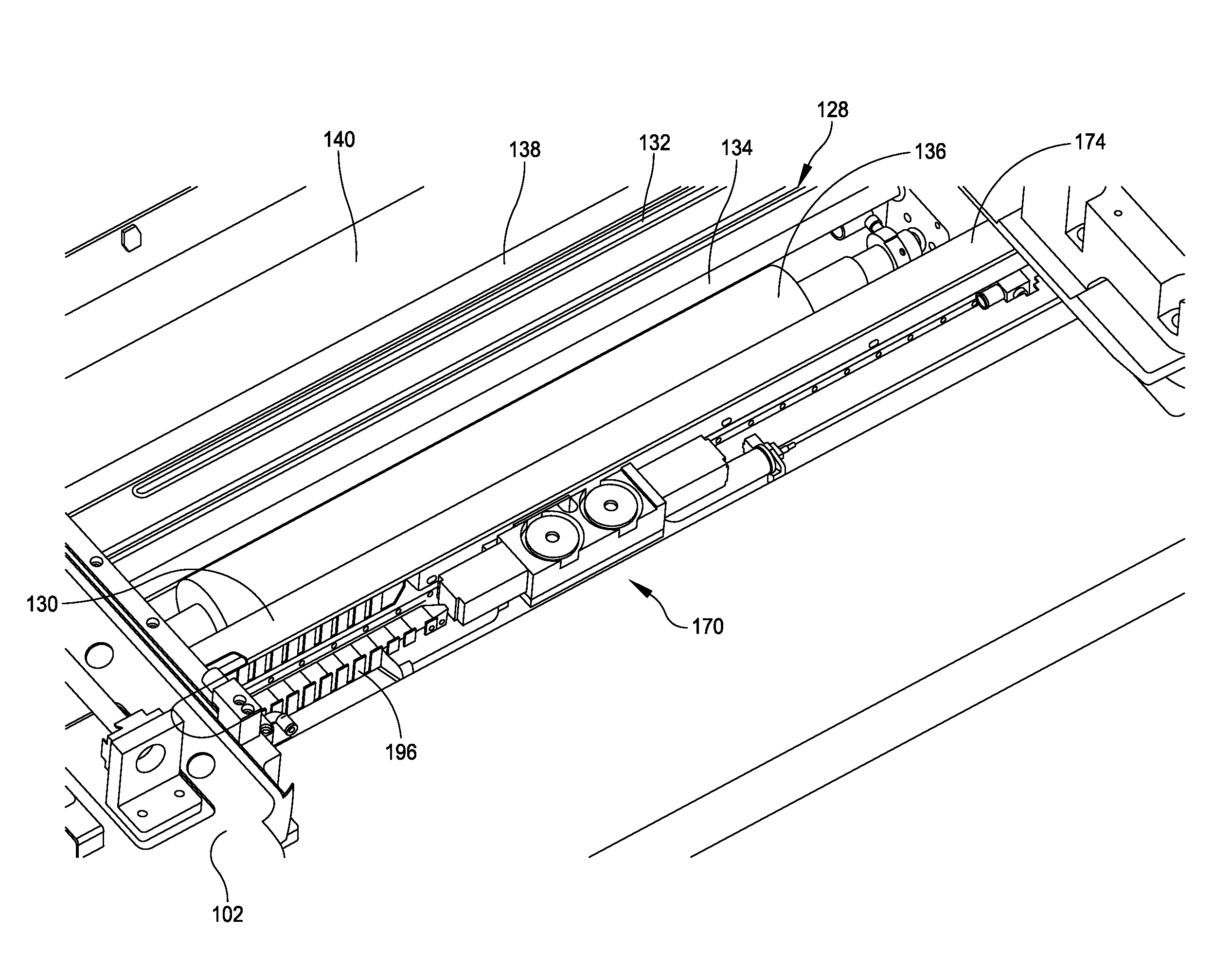
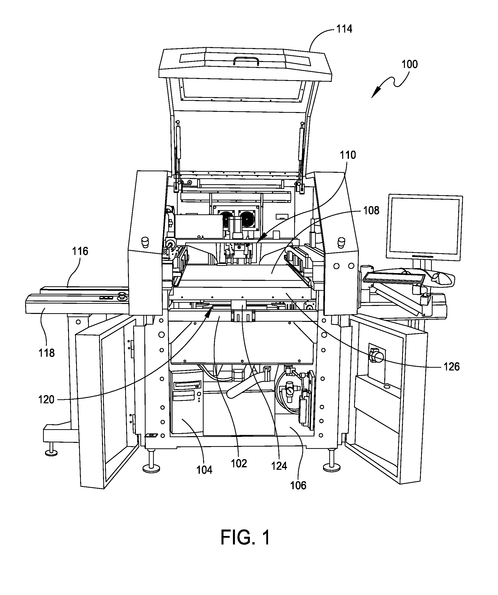
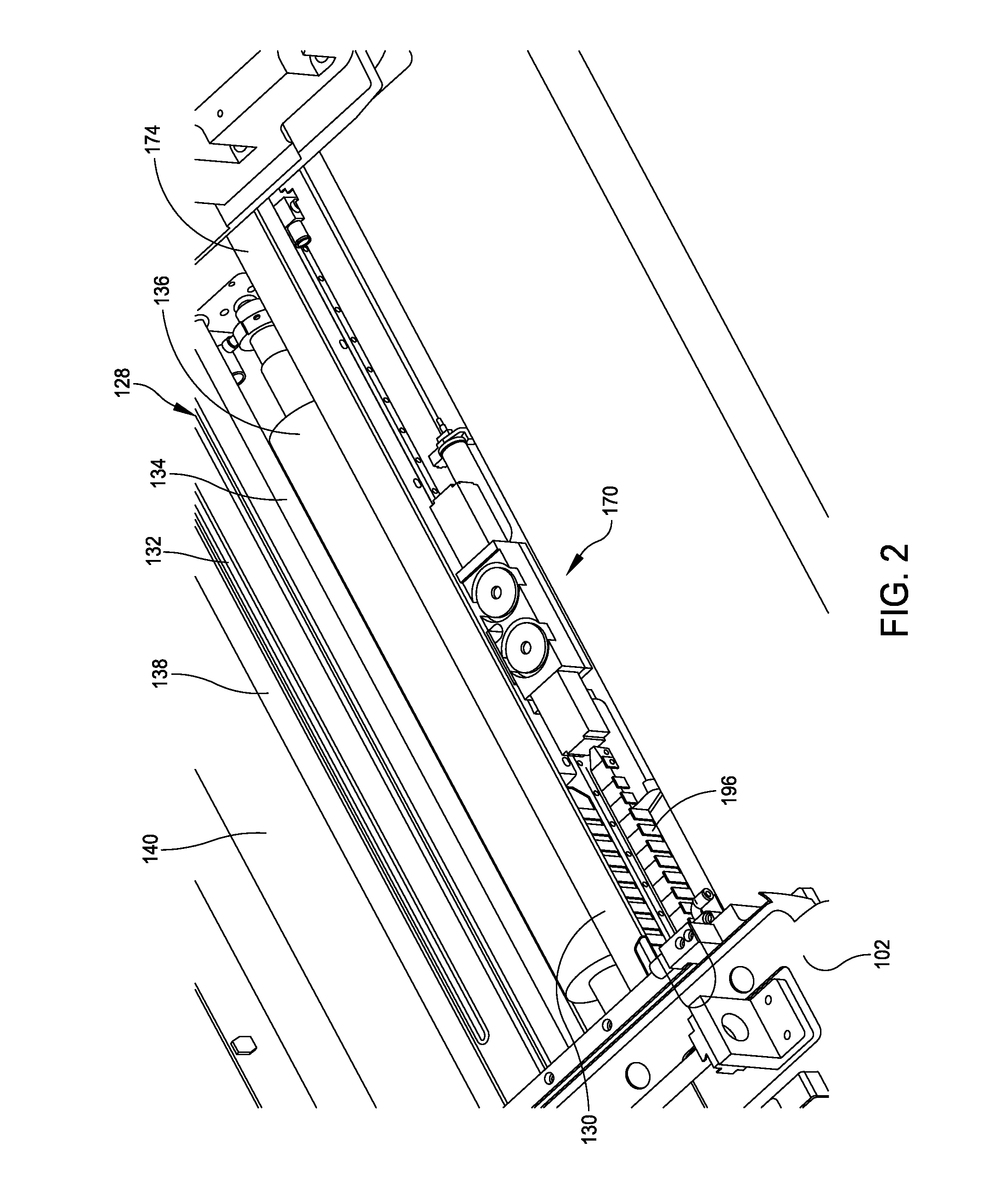
[0034]The present disclosure relates generally to material application machines, such as stencil printers, which may otherwise be referred to as “screen printers,”“printing machines” or “printers.” The present disclosure further relates to dispensers, such as traditional dispensers employing auger screw dispensers or dispensers employing a device capable of jettin...


PUM


Abstract

A combination stencil printer and dispenser includes a frame, a stencil coupled to the frame, a substrate support coupled to the frame to support a substrate in a print position, and a print head coupled to the frame to deposit and print viscous material over the stencil. In one embodiment, the combination stencil printer and dispenser further includes a cleaning assembly coupled to the frame to wipe excess viscous material from a bottom surface of the stencil. The combination stencil printer and dispenser further includes a dispenser mounted on the cleaning assembly to dispense viscous material on the substrate when the substrate is in the print position. In other embodiments, the dispenser can be mounted on a movable stencil or on an independent gantry provided within the combination stencil printer and dispenser.

Description

CROSS-REFERENCE TO RELATED APPLICATIONS[0001]This application relates to U.S. patent application Ser. No. ______ entitled COMBINATION STENCIL PRINTER AND DISPENSER AND RELATED METHODS (Attorney Docket No. M2010-732219), by Dennis G. Doyle, filed on even date herewith, U.S. patent application Ser. No. ______ entitled COMBINATION STENCIL PRINTER AND DISPENSER AND RELATED METHODS (Attorney Docket No. M2010-732319), by Dennis G. Doyle, filed on even date herewith, and U.S. patent application Ser. No. ______ entitled METHODS FOR DEPOSITING VISCOUS MATERIAL ON A SUBSTRATE WITH A COMBINATION STENCIL PRINTER AND DISPENSER (Attorney Docket No. M2010-732419), by Dennis G. Doyle, filed on even date herewith. All of these related applications are incorporated herein by reference.BACKGROUND OF THE INVENTION[0002]1. Field of Disclosure[0003]This disclosure relates generally to methods and apparatus for printing and dispensing viscous material, such as solder paste, onto a substrate, such as a pri...

Claims


Application Information

Patent Timeline
Patent Type & Authority Applications(United States)
IPC IPC(8): B41M1/12B41F35/00
CPCB41F15/12B41M1/12H05K7/02H05K3/1216B41P2235/24H05K3/12H05K3/22
Inventor DOYLE, DENNIS G.
Owner ILLINOIS TOOL WORKS INC
Why Eureka
Try Eureka