Method and apparatus for controlling time of flight confidence map based depth noise and depth coverage range

a technology of depth coverage and depth confidence, applied in the direction of distance measurement, instruments, using reradiation, etc., can solve the problems of affecting the stability of led pulse modulation status, affecting the stability of led pulse modulation, and affecting the accuracy of the depth coverage rang

Active Publication Date: 2012-05-17
TEXAS INSTR INC
View PDF6 Cites 25 Cited by
  • Summary
  • Abstract
  • Description
  • Claims
  • Application Information

AI Technical Summary

Benefits of technology

[0010]Embodiments of the present invention relate to a method and apparatus for fixing a depth map wrap-around error by a confidence map. The method includes dynamically determining a threshold for the confidence map threshold based on an ambient light environment, wherein the threshold is reconfigurable depending on LED light strength distribution in TOF sensor, extracting, via the digital processor, four phases of Time Of Flight raw data from the Time Of Flight sensor data, computing a phase differential signal array for fixed point utilizing the four phases of the Time Of Flight raw data, computing the depth map, confidence map and the average light signal strength utilizing the phase differential signal array, obtaining the dynamic confidence map threshold for wrap around error correction utilizing the average light signal strength, and correcting the depth map wrap-around error utilizing the depth map, the confidence map and the dynamic confidence map threshold.

Problems solved by technology

As a result, a wrap-around error may occur.
The higher is the LED pulse modulation frequency, the more expensive is the cost of TOF parts and the more difficult is having a stable LED pulse modulation status, even though higher LED pulse modulation allows more fine grained precision in depth map resolution.
However, the problem is an aliasing error.
Specifically, in an automobile vision application, Time Of Flight depth map aliasing error can generate significant vision system mal-function.

Method used


Image

  • Method and apparatus for controlling time of flight confidence map based depth noise and depth coverage range
  • Method and apparatus for controlling time of flight confidence map based depth noise and depth coverage range
  • Method and apparatus for controlling time of flight confidence map based depth noise and depth coverage range

Examples


Embodiment Construction

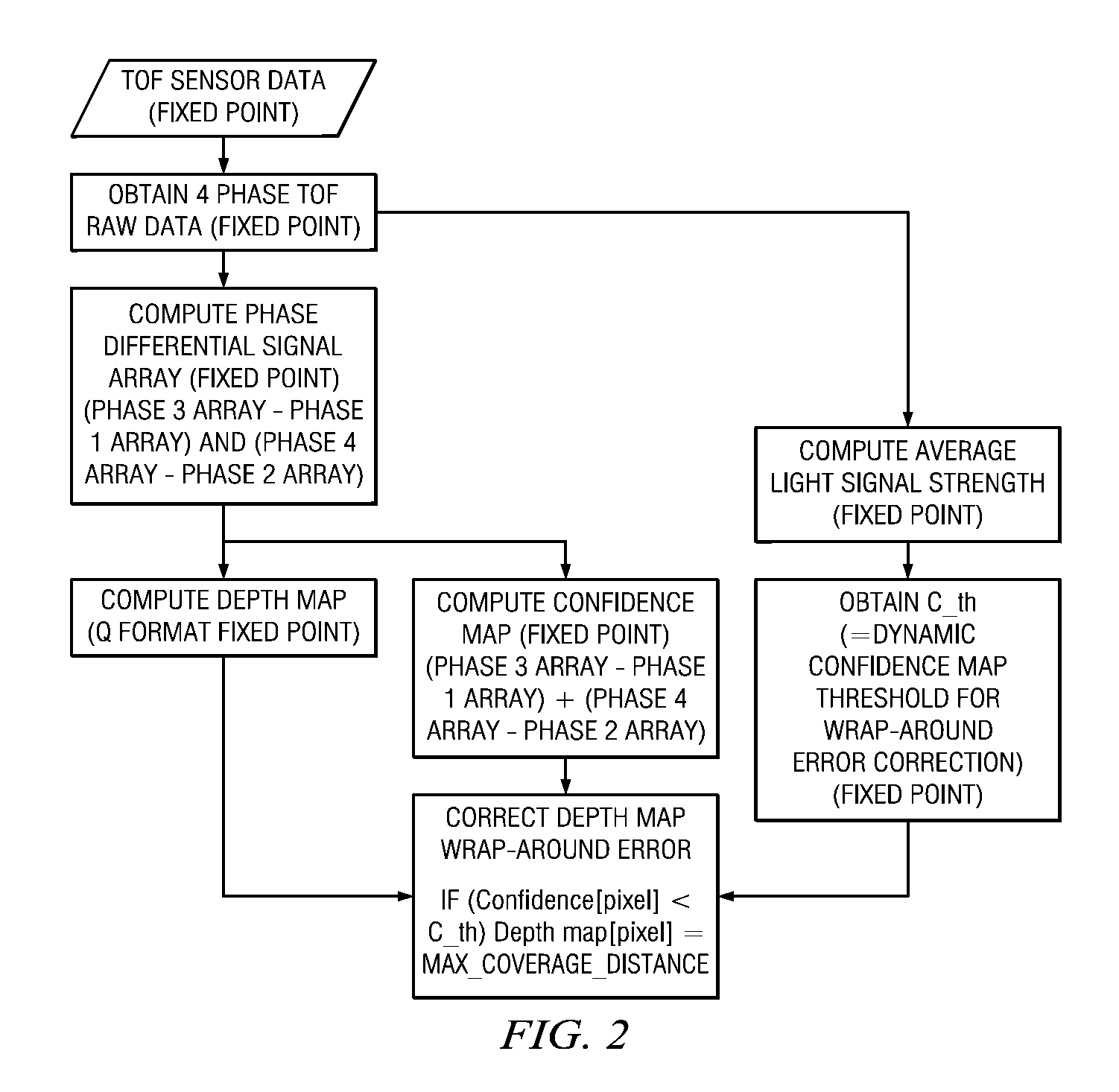
[0018]We propose using a confidence map to control these problems. Confidence map can be built by measuring the strength of sensor data captured. This confidence map can be obtained as a by-product while computing depth map without extra computation cycles. Ultimately, the confidence map has the information of the captured LED light's signal strength.

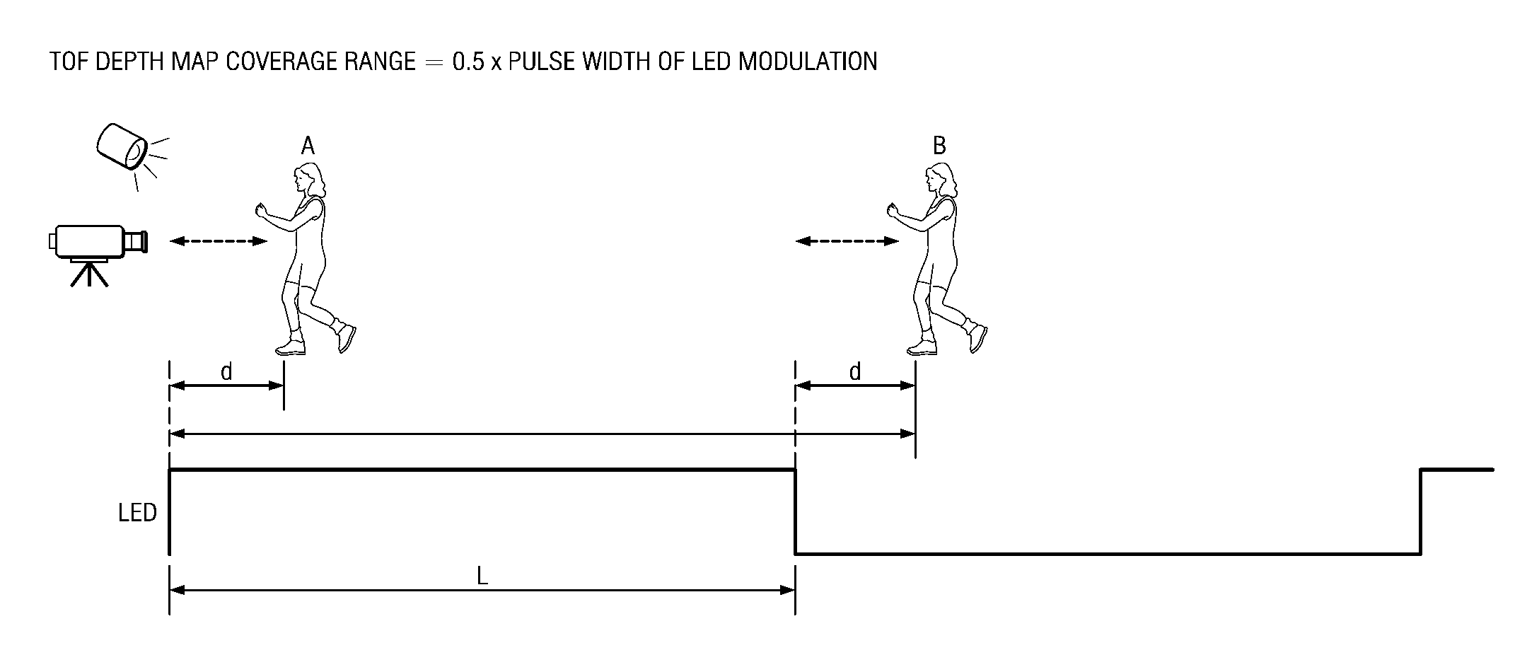
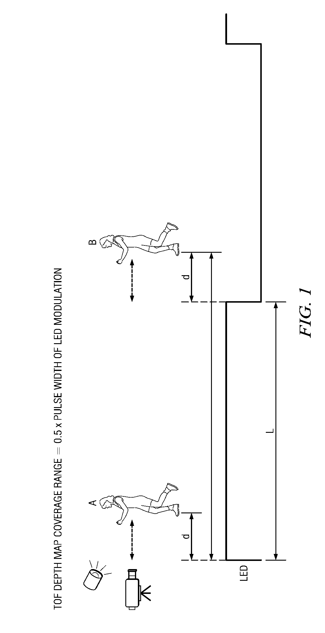
[0019]FIG. 1 is an embodiment of a Time of Flight sensor wrap-around error. FIG. 1 shows a wrap-around error problem. Here, object “A” and object “B” are placed each “d” distance and “L+d” distance away from TOF sensor. Here, “L” is a half of LED pulse width. However, in a phase shift based TOF sensor depth map calculation, “A” and “B” are considered the same distance from TOF sensor. This problem repeats for every “L” distance.

[0020]However, even if a phase shift of “A” and “B” are same, each “A” and “B” has different light signal strength because a reflected light from object “A” close to LED source will be more stronger than “B”.

[002...


PUM


Abstract

A method and apparatus for fixing a depth map wrap-around error and a depth map coverage by a confidence map. The method includes dynamically determining a threshold for the confidence map threshold based on an ambient light environment, wherein the threshold is reconfigurable depending on LED light strength distribution in TOF sensor, extracting, via the digital processor, four phases of Time Of Flight raw data from the Time Of Flight sensor data, computing a phase differential signal array for fixed point utilizing the four phases of the Time Of Flight raw data, computing the depth map, confidence map and the average light signal strength utilizing the phase differential signal array, obtaining the dynamic confidence map threshold for wrap around error correction utilizing the average light signal strength, and correcting the depth map wrap-around error utilizing the depth map, the confidence map and the dynamic confidence map threshold.

Description

CROSS-REFERENCE TO RELATED APPLICATIONS[0001]This application claims benefit of U.S. provisional patent application Ser. Nos. 61 / 413,235 and 61 / 413,247 filed Nov. 12, 2010, which are herein incorporated by reference.BACKGROUND OF THE INVENTION[0002]1. Field of the Invention[0003]Embodiments of the present invention generally relate to a method and apparatus for controlling Time Of Flight confidence map based depth noise.[0004]2. Description of the Related Art[0005]Time Of Flight based sensor measures a depth map by measuring a round trip time of pulse modulated LED light from a camera to the target object point. Usually, the depth map's coverage range corresponds to a half length of LED pulse.[0006]As a result, a wrap-around error may occur. In other words, any object beyond the coverage range of Time Of Flight camera is mistreated as close to Time Of Flight sensor. Time Of Flight camera's depth calculation is based on the phase shift of light, which may be repeated for every a half...

Claims


Application Information

Patent Timeline
Patent Type & Authority Applications(United States)
IPC IPC(8): G06F19/00G16Z99/00
CPCG01S17/36G01S17/89G01D18/00G06F17/40G01C25/00G06F19/00G01C3/00G16Z99/00G01S17/894
Inventor KO, DONG-IKWON, NARANAG, DEBASISH
Owner TEXAS INSTR INC
Why Eureka
Try Eureka