
LDPC post-processor architecture and method for low error floor conditions

Active Publication Date: 2017-05-25
TEXAS INSTR INC
View PDF5 Cites 27 Cited by
  • Summary
  • Abstract
  • Description
  • Claims
  • Application Information

AI Technical Summary

Benefits of technology

The invention aims to solve the problems of error floor that plague the design of data storage devices and high-speed communication systems requiring low error rates. It introduces a post-processing system and method that is more effective in identifying and correcting decoding errors in the low bit error region, improving accuracy and reliability of the data. Additionally, it provides a wider range of error types that can be resolved, further enhancing the efficiency and precision of the post-processing process.

Problems solved by technology

This is undesirable for wireless backhaul customers.
More generally, error floor issues are a concern in any system requiring very low bit error rates.)
A trapping set error causes the decoder to be trapped in a local minimum with respect to a “cost function” that characterizes the quality of the decoder output.
The difficult problems lie in practical implementation of the decoding process.
It is well-known that LDPC decoders suffer from the previously mentioned error floor problems.
Over the past decade, it has been found that the excellent performance of LDPC is only observed up to a moderate bit error rate (BER), leading to the previously mentioned “error floor”.
Solving the error floor problem has been a critical issue for both coding theorists and practitioners, since more and more systems, such as data storage devices and high-speed communications systems, require extremely low error rates.
Past experiments have shown that error floors can be caused by various practical decoder implementations.
However, error floors are fundamentally attributed to non-codeword “trapping sets” associated with LDPC codes.
Although these methods are effective, the resulting code structures often complicate the decoder hardware design.
An alternative way is to improve the BP decoding algorithm by methods such as scaling, offsetting, or trial and error, but these methods are mostly based on heuristics and their effectiveness is limited.
Some of these methods even require extra steps that are incompatible with BP decoding, leading to a higher complexity and much longer latency (the time it takes for the decoder to produce the decoded codeword).
Furthermore, the prior art in post-processing hardware only allows changing magnitude of the noise.
In the error floor region, the prior art LDPC decoders cannot successfully decode certain received codewords.
Prior art post-processing helps the decoder decode some of these failures, but the real goal is to be able to decode all of the failures, and unfortunately, the techniques of the prior art can only resolve a limited type and number of errors.
This consequently directly limits the amount of error floor improvement that as a practical matter is achievable by the prior art.

Method used


Image

  • LDPC post-processor architecture and method for low error floor conditions
  • LDPC post-processor architecture and method for low error floor conditions
  • LDPC post-processor architecture and method for low error floor conditions

Examples


Embodiment Construction

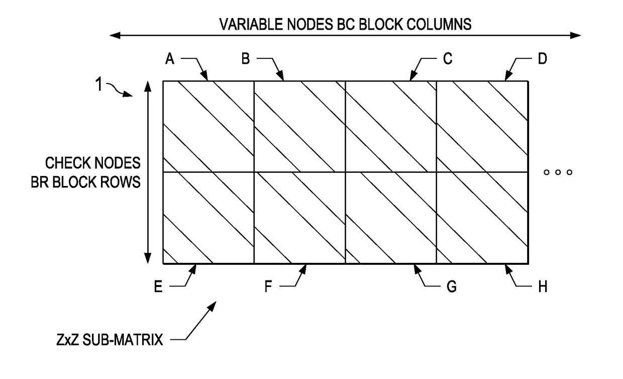
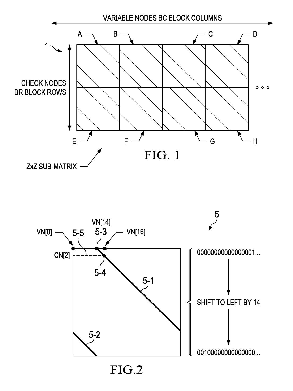
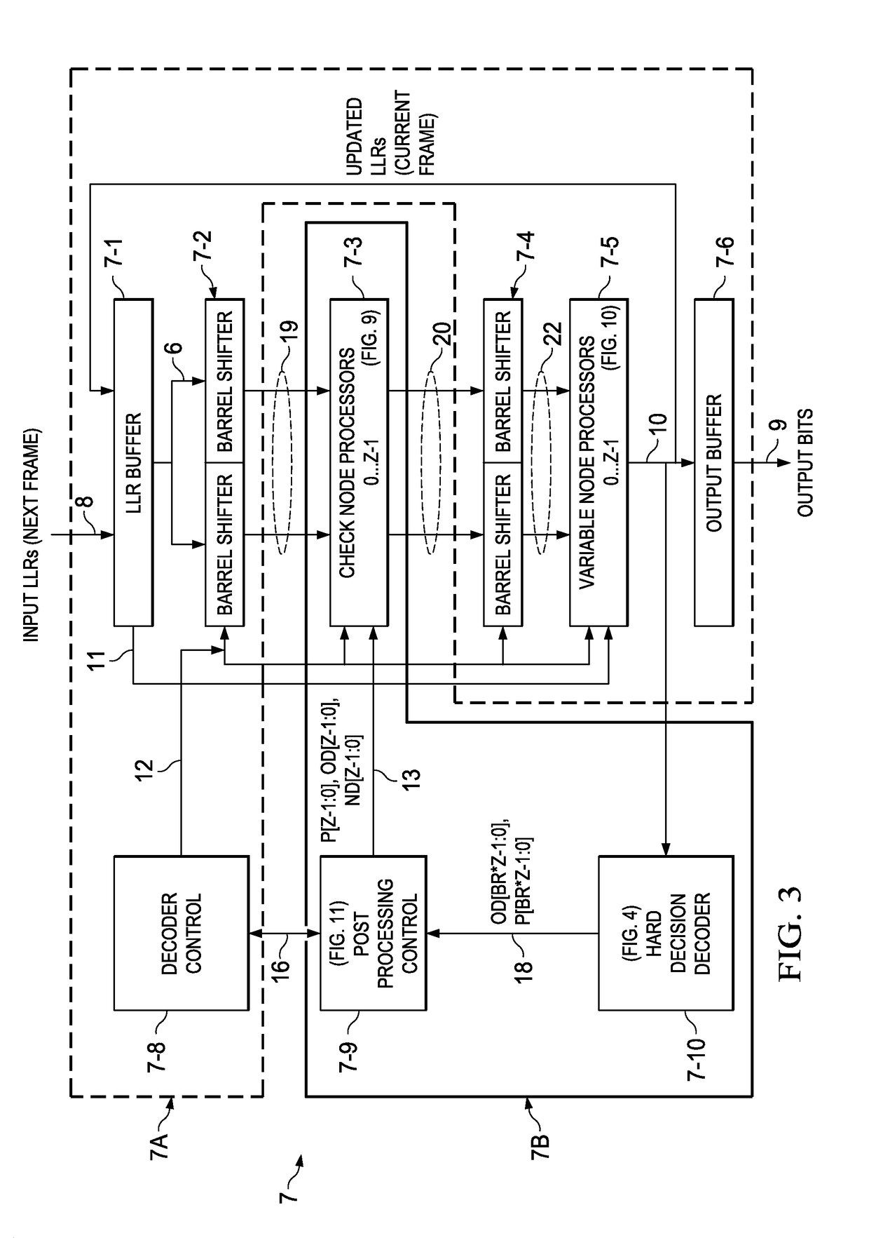
[0055]This invention describes hardware that implements a new post-processing algorithm for addition to a high-throughput LDPC decoder. One embodiment of the new hardware post-processor implementation is designed for error floor mitigation in a parallel QC-LDPC (“Quasi-Cyclic” LDPC) decoder. The post-processing algorithm injects noise of controllable duration (and also controllable magnitude, if desired) into the decoder to help the decoder output converge to a valid codeword. The post-processing algorithm can be applied to QC-LDPC decoder architectures and also to other types of decoder architectures. In one embodiment, the post-processing algorithm and hardware may operate to lower the error floor by a factor of nearly 10.

[0056]As previously indicated, some LDPC codes are known to exhibit error floors (i.e. a reduction in the slope of the bit error rate (BER) versus channel signal-to-noise ratio (SNR) curve) at low BER levels. This implies that in the error floor region, a large i...


PUM


Abstract

Post-processing circuitry for LDPC decoding includes check node processor for processing shifted LLR values, a hard decision decoder circuitry for receiving processed LLR information and performing parity checks on the processed LLR information. Post-processing control circuitry controls updating of LLR information in the check node processor. The check node processor, hard decision decoder, and control circuitry cooperate to identify check nodes with unsatisfied parity checks after an iteration cycle, identify neighborhood variable nodes that are connected with unsatisfied check nodes, identify satisfied check nodes which are connected to neighborhood variable nodes, and modify messages from neighborhood variable nodes to satisfied check nodes if needed to introduce perturbations to resolve decoding errors. Neighborhood identification circuitry determines which variable nodes are connected with unsatisfied check nodes, that have failed a parity check, and produces a signal indicating which variable nodes are connected to unsatisfied check nodes.

Description

BACKGROUND OF THE INVENTION[0001]The present invention relates generally to hardware and software additions to an LDPC (Low Density Parity Check) decoder to implement a post-processing algorithm, and more particularly to additions which inject noise into the decoder to help it converge to a valid codeword and thereby lower the error floor.[0002]Some Low Density Parity Check (LDPC) codes show an “error floor”, which is a reduction in the slope of the BER (Bit Error Rate) vs. channel SNR (signal-to-noise) curve, at low BER levels. This implies that the bit error rate at a given signal-to-noise ratio is higher than expected. This is undesirable for wireless backhaul customers. (The term “wireless backhaul” refers to communication links between cellular base-stations. It is a technology that is linked with carrying communication traffic among sites that are spaced in a circular manner, and is also used for two-way data transmission lines. More generally, error floor issues are a concern...

Claims


Application Information

Patent Timeline
IPC IPC(8): H03M13/11
CPCH03M13/1117H03M13/1142H03M13/1108H03M13/1111H03M13/116
Inventor TAO, YAOYUKWONG, JOYCE
Owner TEXAS INSTR INC
Learn More