Assembly equipment and construction technology for a restrained concrete arch frame

A technology for confining concrete and assembling equipment, which is applied to vertical shaft equipment, mining equipment, earthwork drilling and mining, etc. It can solve problems such as insufficient support bearing capacity, effective control of surrounding rock, and inaccurate positioning, so as to achieve reasonable selection of adjustment position points, The effect of reducing the instability of the face and making the equipment easy to operate

Active Publication Date: 2019-09-20
UNIV OF JINAN +1
View PDF5 Cites 0 Cited by
  • Summary
  • Abstract
  • Description
  • Claims
  • Application Information

AI Technical Summary

Problems solved by technology

[0002] With the rapid development of the scale and speed of underground engineering construction, the tunnels planned during the construction process will inevitably pass through strata with complex conditions such as high stress and weak fracture zones. Traditional support methods are difficult to meet the actual needs of the site.
Therefore, when the constrained concrete arch is used as a new type of support to replace the original steel support, there are problems such as inaccurate positioning and difficulty in adjusting the position, and it is easy to cause problems such as out-of-plane instability under the action of surrounding rock, resulting in support Insufficient protective capacity
At the same time, during the blasting process of the face, there are phenomena such as over-excavation at the arch foot, which also has a considerable impact on the positioning of the arch. Inaccurate positioning may not be able to effectively control the surrounding rock, and in severe cases, it will cause the face to become unstable. , Tunnel collapse, causing major economic losses

Method used


Image

  • Assembly equipment and construction technology for a restrained concrete arch frame
  • Assembly equipment and construction technology for a restrained concrete arch frame
  • Assembly equipment and construction technology for a restrained concrete arch frame

Examples


Embodiment Construction

[0051] The present invention will be further described below in conjunction with the accompanying drawings and embodiments.

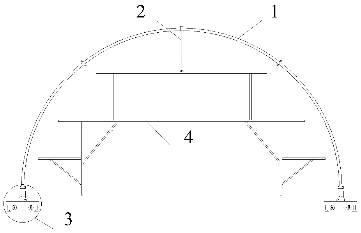
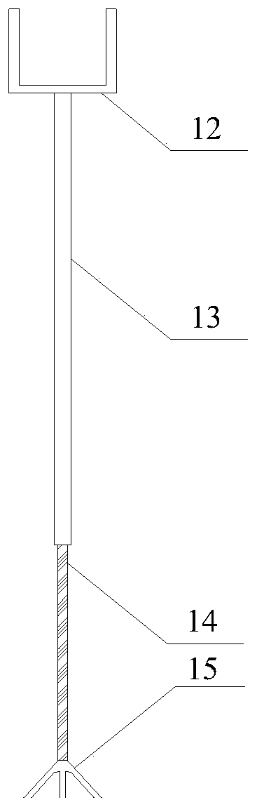
[0052] An assembly device for a constrained concrete arch, including: a constrained concrete arch formwork, which forms a closed space for pouring concrete inside; a positioning operation trolley for adjusting the arch legs on the ground 3. Adjusting the position of the arch The support frame 2, and the laser aligner 18 arranged on the vault and the arch feet on both sides.

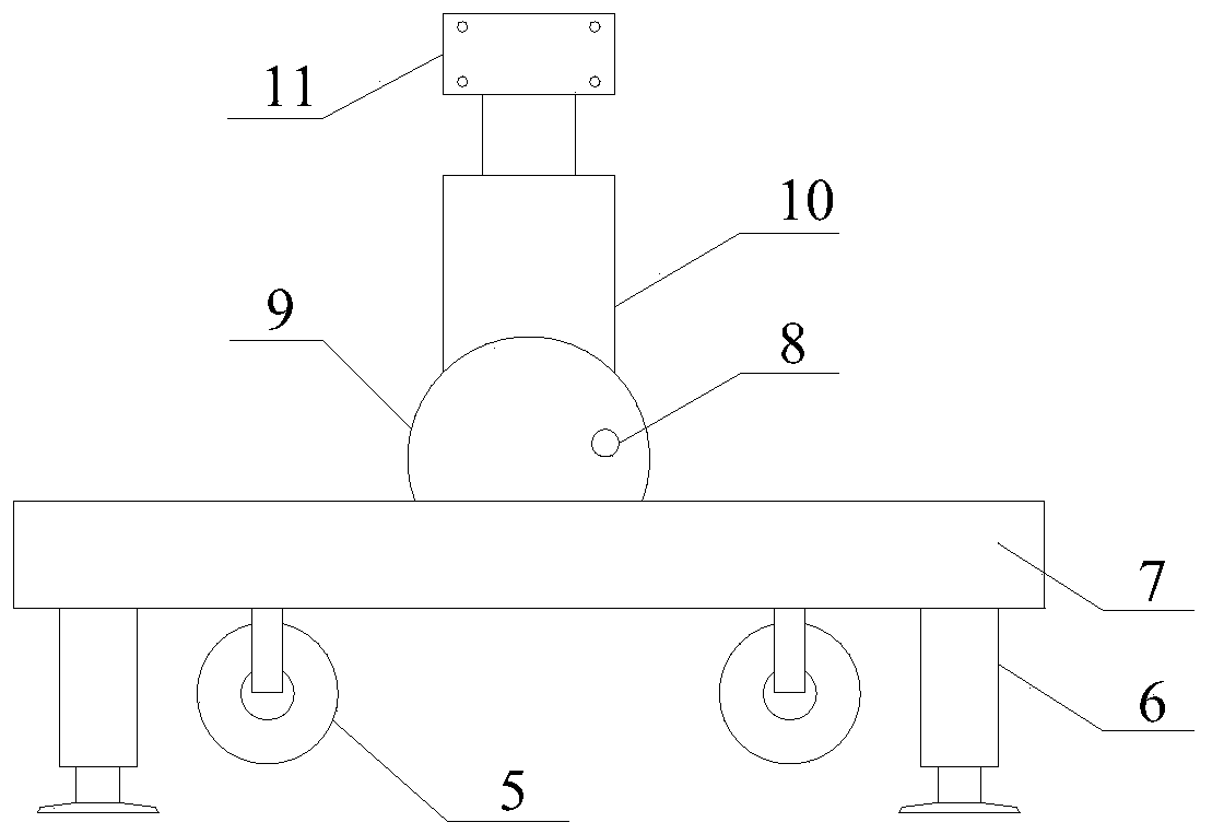
[0053] The positioning operation trolley 3 adjusts the arch legs, specifically including the bottom load-bearing structure composed of tires 5, jacks and platforms 7, the middle support structure composed of rotatable and fixed position adjustment jacks 10, and the upper clamp for constraining the arch legs. Support structure11. Among them, the bearing structure at the bottom of the positioning operation trolley 3 is based on the general tire 5 and platform structure, and four bot...


PUM


Abstract

The invention discloses an assembly device and construction technology for a restraining concrete arch frame. The assembly device comprises a restrained concrete arch frame formwork, a vault adjustingdevice, two adjusting trolleys, and a laser aligning system. A sealed space for pouring concrete is formed in the restrained concrete arch frame formwork, and the vault adjusting device is arranged at the vault position of the restrained concrete arch frame formwork. The two adjusting trolleys are separately used for adjusting and locating two arch legs of the restrained concrete arch frame formwork, the two adjusting trolleys specifically comprise upper clamping components and adjusting supporting components, wherein the upper clamping components are provided with upward opening parts used for clamping the arch legs; and the adjusting supporting components can stretch and retract in the axial direction, the tops of the adjusting supporting components are fixedly connected with the bottoms of the upper clamping components, and the bottoms of the adjusting supporting components is fixedly connected with a load-bearing platform in a rotating mode along the vertical plane. The laser aligning system comprises laser launching receiving devices which are separately arranged on the vault adjusting device and the adjusting trolleys, and the degree of accuracy of the locating of the arch frame is determined based on laser receiving states of each laser launching receiving device and the relationship between the laser receiving states and a vertical positioning hammer arranged on the arch frame.

Description

technical field [0001] The invention relates to the technical field of underground engineering construction, in particular to assembly equipment and a construction process for constrained concrete arches. Background technique [0002] With the rapid development of the scale and speed of underground engineering construction, the tunnels planned during the construction process will inevitably pass through strata with complex conditions such as high stress and weak fracture zones. Traditional support methods cannot meet the actual needs of the site. Therefore, when the constrained concrete arch is used as a new type of support to replace the original steel support, there are problems such as inaccurate positioning and difficulty in adjusting the position, and it is easy to cause problems such as out-of-plane instability under the action of surrounding rock, resulting in support Insufficient protective capacity. At the same time, during the blasting process of the face, there a...

Claims


Application Information

Patent Timeline
Patent Type & Authority Patents(China)
IPC IPC(8): E21D11/10E21D11/40
Inventor 江贝王琦栾英成高莉李术才李晓亮孙会彬鹿伟秦乾于恒昌
Owner UNIV OF JINAN
Why Eureka
Try Eureka