
A precision installation and adjustment method for ton-level optical-mechanical components
An installation adjustment and optical-mechanical technology, applied in installation, optical components, engine frame, etc., can solve problems such as long time-consuming, irregularities to follow, and different installation and adjustment methods, so as to ensure surface cleanliness and positioning accuracy , Improve the effect of adjustment efficiency
- Summary
- Abstract
- Description
- Claims
- Application Information
AI Technical Summary
Problems solved by technology
Method used
Image

Examples
Embodiment 1
[0036] A precision installation and adjustment method for ton-level optical-mechanical components, comprising the following steps:
[0037] S1. After the optical-mechanical component enters the installation station, use the coordinate measuring equipment to test the external target of the optical-mechanical component to obtain the actual measured position of the optical-mechanical component. The measured position is the current position of the optical-mechanical component represented by the coordinate group value of the external target of the test attitude, wherein the coordinate measuring device is preferably a laser tracker.
[0038] S2. Obtain the target position of the optomechanical component by fitting the measured position with the theoretical position, and calculate the adjustment amount. Specifically, the theoretical position is the pose of the optomechanical component represented by the model and drawings. Due to the existence of the error of the optomechanical compon...
Embodiment 2
[0043] The same part of this embodiment and Embodiment 1 will not be described again, the difference is:
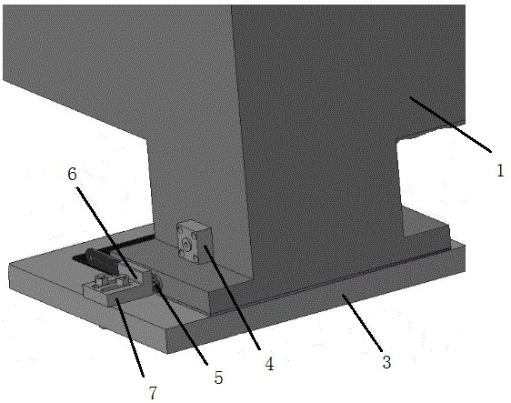
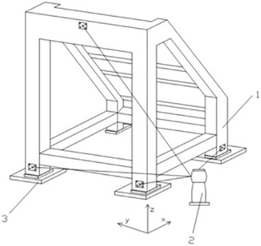
[0044] Such as figure 1 and figure 2As shown, when the supporting device of the optomechanical component is the supporting tool 1, the 6 independent quantities include 3 Z-direction adjustments, 2 X-direction adjustments and 1 Y-direction adjustment, and the supporting tool 1 is set below There are 4 outriggers, select the 3 outriggers that coordinate measuring equipment 2 can see through as the adjustment outriggers, set the target seat 4 on the adjustment outriggers, set the support plate 3 under the adjustment outriggers, and correspond to the adjustment outriggers Offer the fixed block connecting port on the support plate 3.
[0045] Specifically, the coordinate measuring device 2 is used to test the external target of the optomechanical component to obtain the measured position of the optomechanical component. After fitting the measured position and the theoretica...
Embodiment 3
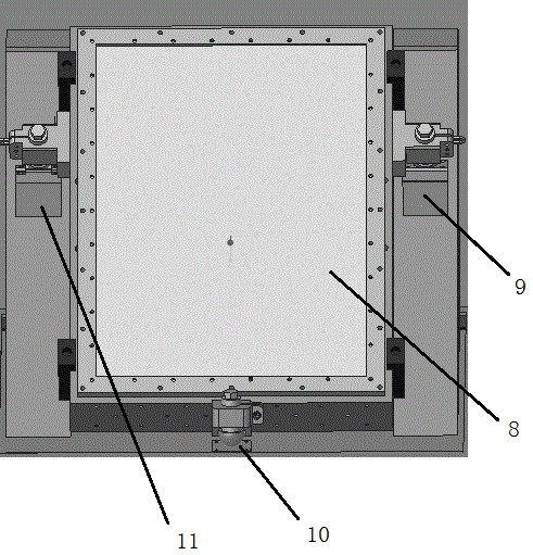
[0051] Such as figure 2 and image 3 As shown, when the supporting device of the optomechanical assembly is a support seat, the target seat is set on the support seat. In this embodiment, the optomechanical assembly is in a tilted state. The supporting seat is a conical support 9, a V-shaped support 11 and a plane support 10, and at the same time, a support plate is provided under the conical support 9, the V-shaped support 11 and the plane support 10. The 6 independent quantities include 3 Z-direction adjustments, 2 Y-direction adjustments and 1 X-direction adjustment. To adjust the X-direction of the conical support 9 or V-shaped support 11 or plane support 10, this In the embodiment, the conical support 9 is adjusted in the X direction, the conical support 9 and the V-shaped support 11 are adjusted in the Y direction, and the conical support 9, the V-shaped support 11 and the plane support 10 are adjusted in the Z direction .
[0052] Specifically, the coordinate measur...
PUM
 Abstract
Description
Claims
Application Information