Drawing table
A technology of drawing tables and table boards, applied in the field of drawing tables, can solve the problems of lost drawing and inconvenience of drawing, and achieve the effect of convenient storage and storage, smooth drawing and convenient drawing
- Summary
- Abstract
- Description
- Claims
- Application Information
AI Technical Summary
Problems solved by technology
Method used
Image

Examples
Embodiment 1
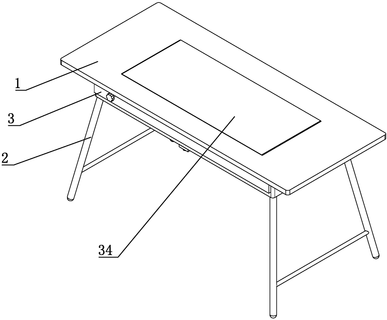
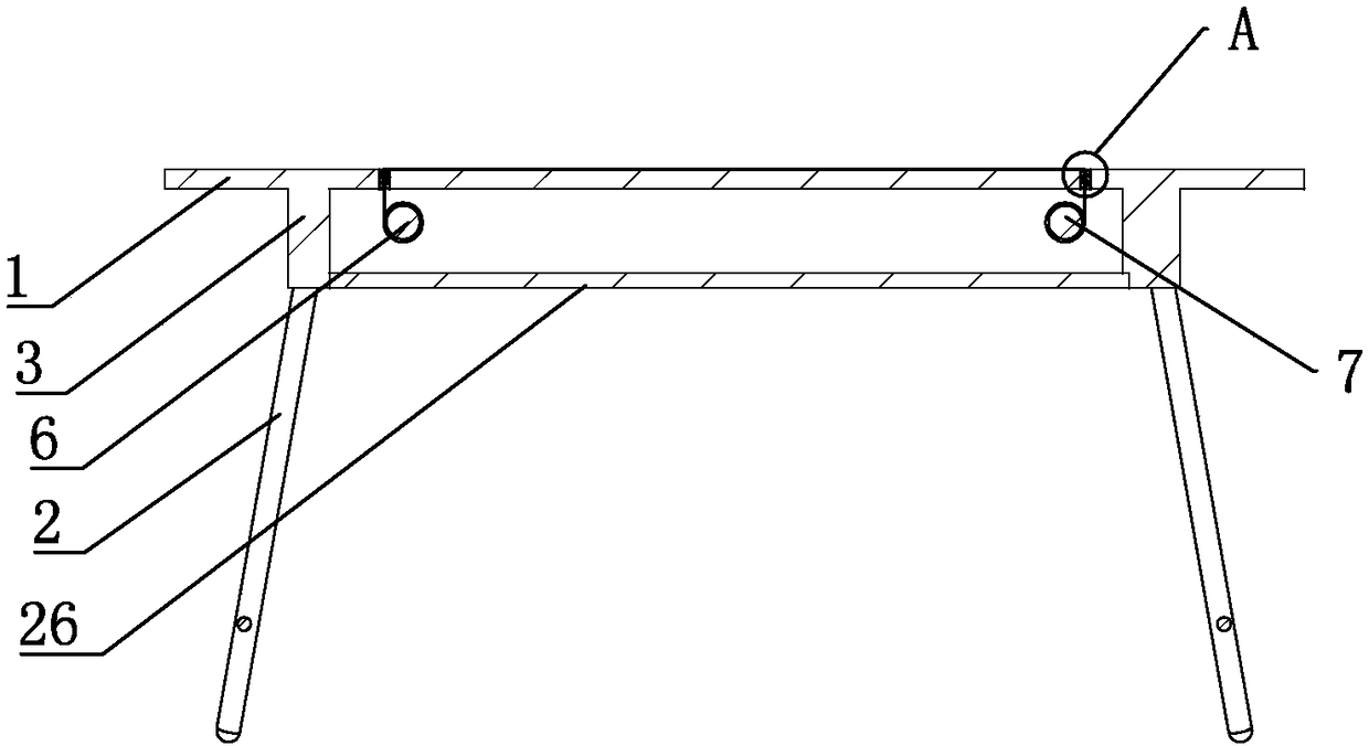
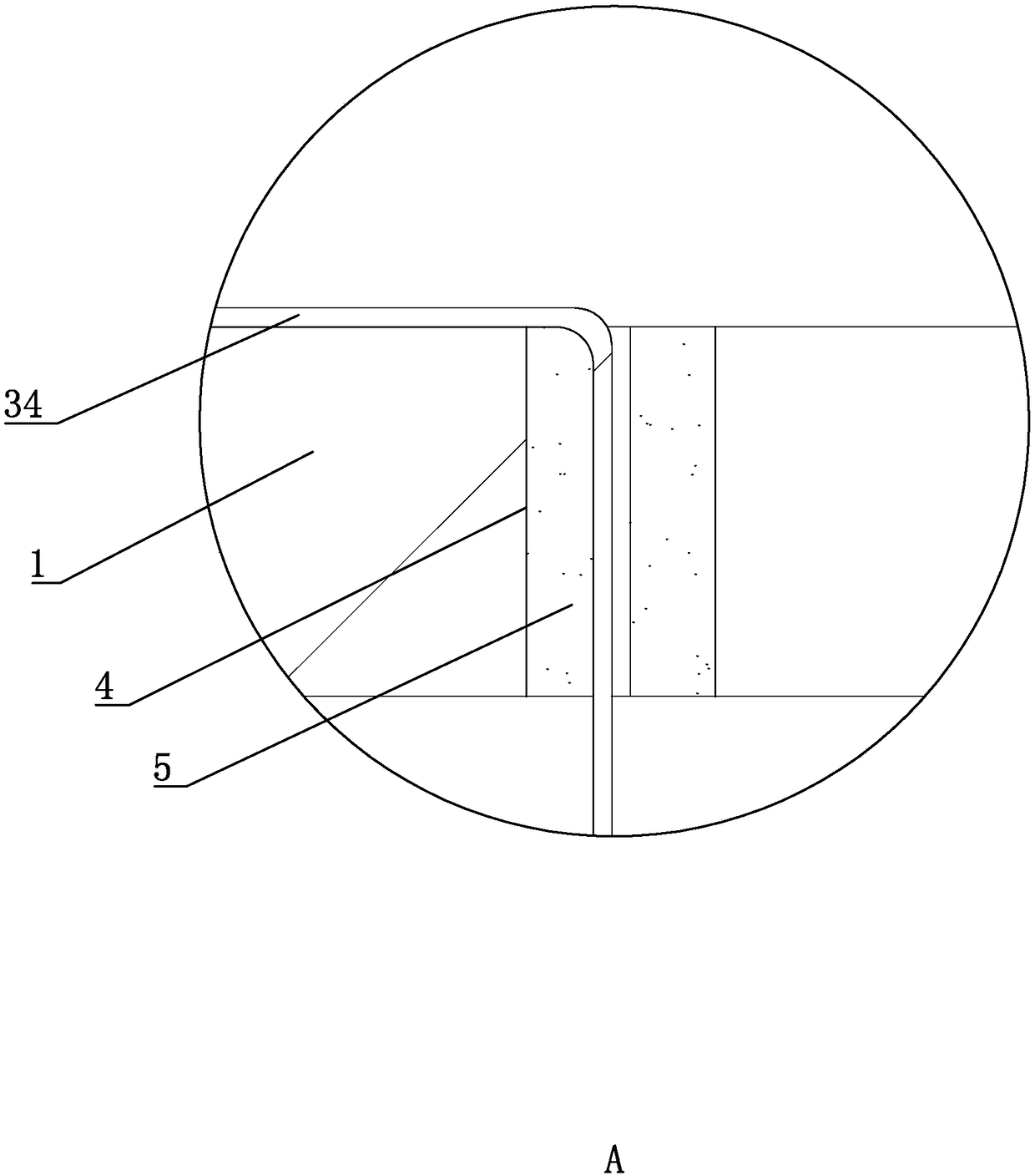
[0050] Such as figure 1 and figure 2 As shown, a drawing table includes a table board 1 and table feet 2 for supporting the table board 1. The lower end of the table board 1 is fixedly equipped with a receiving box 3 with an opening downward. Such as image 3 As shown, the table 1 is provided with through grooves 4 , two through grooves 4 are located on both sides of the table 1 respectively, and the inner wall of the through groove 4 is provided with a flexible pad 5 . An unwinding roller 6 and a winding roller 7 are arranged inside the containing box 3 along the width direction of the containing box 3 , and the unwinding roller 6 and the winding roller 7 are located on the left and right sides of the containing box 3 respectively. Drawings 34 are rewound on the unwinding roller 6 . Drawing 34 is far away from unwinding roller 6 one end and passes through slot 4 to the top of table top 1, passes back table top 1 bottom through another slot 4 again, and then winds up on w...
Embodiment 2
[0066] Such as Figure 8 As shown, a drawing table includes a table board 1 and table feet 2 for supporting the table board 1. The lower end of the table board 1 is fixedly equipped with a receiving box 3 with an opening downward. Such as Figure 9 As shown, the table 1 is provided with through grooves 4 , two through grooves 4 are located on both sides of the table 1 respectively, and the inner wall of the through groove 4 is provided with a flexible pad 5 . An unwinding roller 6 and a winding roller 7 are arranged inside the containing box 3 along the width direction of the containing box 3 , and the unwinding roller 6 and the winding roller 7 are located on the left and right sides of the containing box 3 respectively. Drawings 34 are rewound on the unwinding roller 6 . Drawing 34 is far away from unwinding roller 6 one end and passes through slot 4 to the top of table top 1, passes through another slot 4 and goes back under table top 1 again, and then winds up on windin...
Embodiment 3
[0085] The difference between Embodiment 3 and Embodiment 1 is that, as Figure 15 As shown, the table board 1 is provided with a flattening rod 28 along the length direction of the drawing 34, and two flattening rods 28 are provided, and the two flattening rods 28 are arranged symmetrically along the center of the table board 1. Such as Figure 16 As shown, sliding plates 29 are provided at both ends of the push rod 28 , and the sliding plates 29 are slidably connected to the table top 1 along the length direction of the drawing 34 .
[0086] Such as Figure 17 As shown, the sliding plate 29 is provided with an embedded groove 30 arranged along the horizontal direction, an introduction groove 31 arranged in an arc and an outlet groove 32 arranged in an arc. The lead-in groove 31 is connected to the end of the insertion groove 30 near the center of the table 1, and the two ends of the lead-out groove 32 are respectively connected to the upper end of the lead-in groove 31 and...
PUM
 Abstract
Description
Claims
Application Information
 - R&D Engineer
- R&D Manager
- IP Professional
- Industry Leading Data Capabilities
- Powerful AI technology
- Patent DNA Extraction
Browse by: Latest US Patents, China's latest patents, Technical Efficacy Thesaurus, Application Domain, Technology Topic.
© 2024 PatSnap. All rights reserved.Legal|Privacy policy|Modern Slavery Act Transparency Statement|Sitemap