Cell oscillation device for cell engineering

A cell engineering, cell technology, applied in the field of cell engineering, can solve the problem of cell solution shock, and achieve the effect of avoiding damage

Active Publication Date: 2018-07-06
居李生物科技(北京)有限公司
View PDF6 Cites 11 Cited by
  • Summary
  • Abstract
  • Description
  • Claims
  • Application Information

AI Technical Summary

Problems solved by technology

However, this utility model cannot shake the cell solution in multiple directions

Method used


Image

  • Cell oscillation device for cell engineering
  • Cell oscillation device for cell engineering
  • Cell oscillation device for cell engineering

Examples


specific Embodiment approach 1

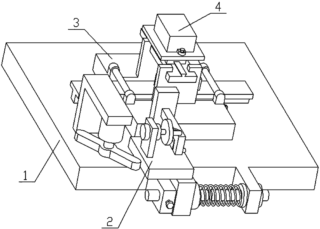
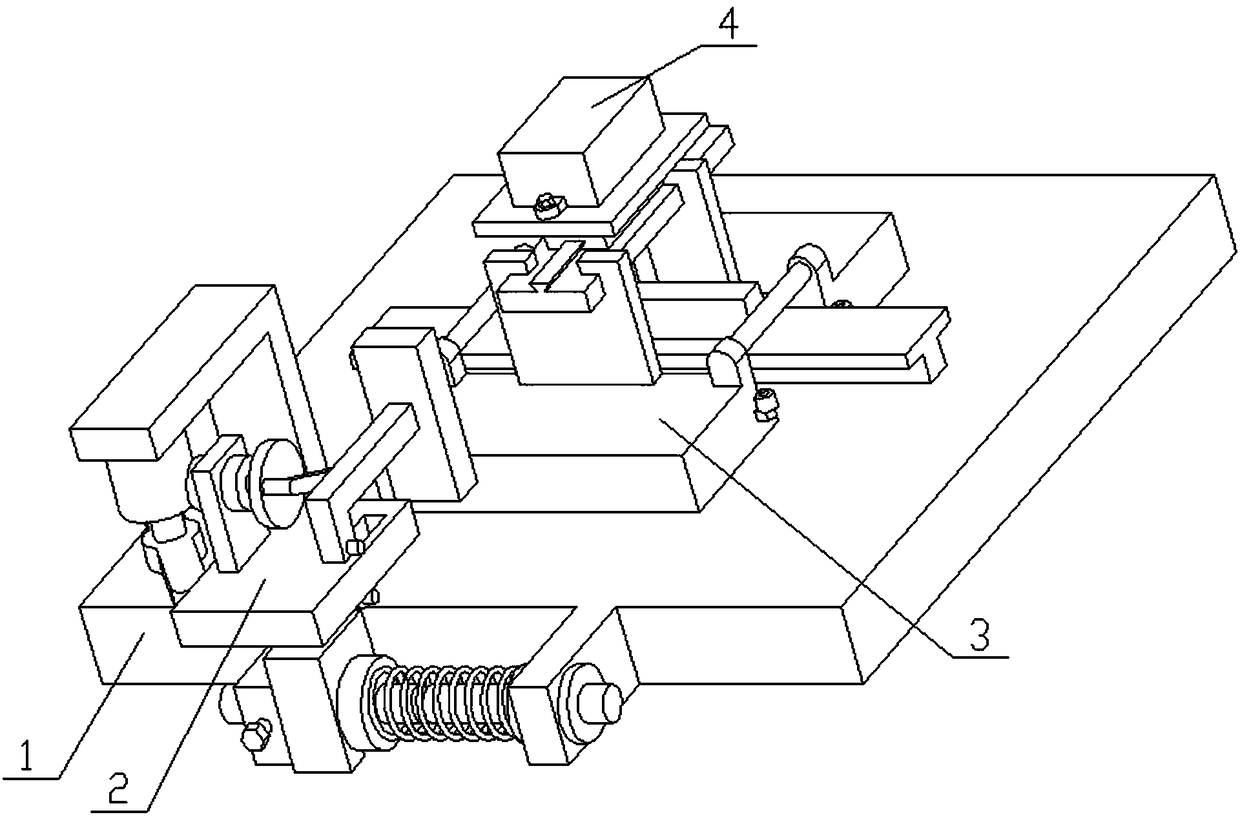
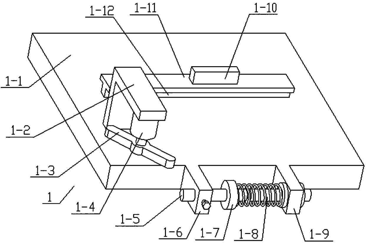
[0027] Combine below Figure 1-11 Describe this embodiment, the present invention relates to the field of cell engineering, more specifically a cell engineering cell vibration device, including a base assembly 1, a power assembly 2, a vibration frame assembly 3 and a container box assembly 4, the sliding seat in the device is both It can be moved forward and backward, and can also be moved left and right, so as to shake the cell solution in multiple directions, avoiding damage to the cells when directly using the stirring blade to stir the cell solution.

[0028] The base assembly 1 includes a bottom plate 1-1, a movable round rod 1-5, a left bump 1-6, a sliding ring 1-7, a fixed round rod 1-8, a right bump 1-9, and a long convex strip 1 -10, horizontal plate 1-11 and vertical plate 1-12, the upper end of bottom plate 1-1 is fixedly connected with vertical plate 1-12, the upper end of vertical plate 1-12 is fixedly connected with horizontal plate 1-11, horizontal plate 1- The...


PUM


Abstract

The invention relates to the field of cell engineering and in particular to a cell oscillation device for cell engineering. A sliding base inside the device can be moved forwards and backwards, and leftwards and rightwards as well, so that a cell solution can be oscillated in multiple directions, and the consequence that cells are damaged since the cell solution is directly stirred by using stirring blades can be avoided. A vertical plate is fixedly connected with the upper end of a bottom plate; a transverse plate is fixedly connected with the upper end of the vertical plate; a long-convex strip is fixedly connected with the upper end of the transverse plate; a left convex block and a right convex block are respectively fixedly connected with the left end and the right end of the front end of the bottom plate; a fixing round rod is fixedly connected with the left end of the right convex block; a moveable round rod is connected with the left convex block in a sliding manner; a fastening screw is in threaded connection with the front end of the left convex block; the fastening screw is connected with the moveable round rod; the moveable round rod is coaxial with the fixed round rod;the radius of the cross section of the moveable round rod is equal to that of the cross section of the fixed round rod; the right end of the moveable round rod is fitted to the left end of the fixedround rod; a sliding ring is connected with the combined rod of the moveable round rod and the fixed round rod in a sliding manner.

Description

technical field [0001] The invention relates to the field of cell engineering, in particular to a cell engineering cell vibration device. Background technique [0002] The application number is CN201521143707.4 for an oscillating and mixing device. This utility model discloses an oscillating and mixing device, including a vortex meter, an oscillating output shaft, a fixed plate, an oscillating box, an oscillating cavity, a switch, a through hole, an upper Cover, cap, buffer pad, adjustment screw and locking mechanism, the front end of the vortex meter is provided with a switch, the top of the vortex meter is provided with an oscillating output shaft, and the top of the oscillating output shaft is provided with a fixed piece, and the fixed The top of the sheet is fixed with a shock box, the shock box is provided with a plurality of shock chambers, the bottom of the shock chamber is provided with a through hole, the upper end of the shock chamber is provided with an upper cove...

Claims


Application Information

Patent Timeline
Patent Type & Authority Applications(China)
IPC IPC(8): C12M3/00
CPCC12M27/16
Inventor 董银
Owner 居李生物科技(北京)有限公司
Why Eureka
Try Eureka