Easily cleaned thermal treatment quenching tank

A quenching pool, easy technology, applied in the field of heat treatment quenching equipment, can solve the problems of affecting work efficiency, wasting a lot of time, inconvenient cleaning, etc., and achieve the effect of improving the effect of physical slag removal

Inactive Publication Date: 2018-07-06
HUBEI ZANBO INFORMATION TECH CO LTD
View PDF0 Cites 2 Cited by
  • Summary
  • Abstract
  • Description
  • Claims
  • Application Information

AI Technical Summary

Problems solved by technology

[0004] The purpose of the present invention is to provide an easy-to-clean heat treatment quenching pool to solve the problem that the structural design proposed in the above-mentioned background technology is relatively traditional and simple, the cleaning is relatively inconvenient, and the cleaning is easy to waste a lot of time and affect the work efficiency.

Method used


Image

  • Easily cleaned thermal treatment quenching tank
  • Easily cleaned thermal treatment quenching tank
  • Easily cleaned thermal treatment quenching tank

Examples


Embodiment

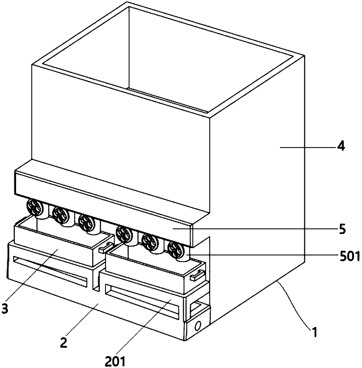
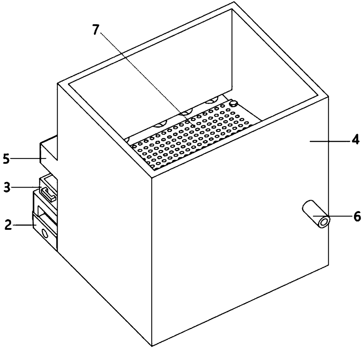
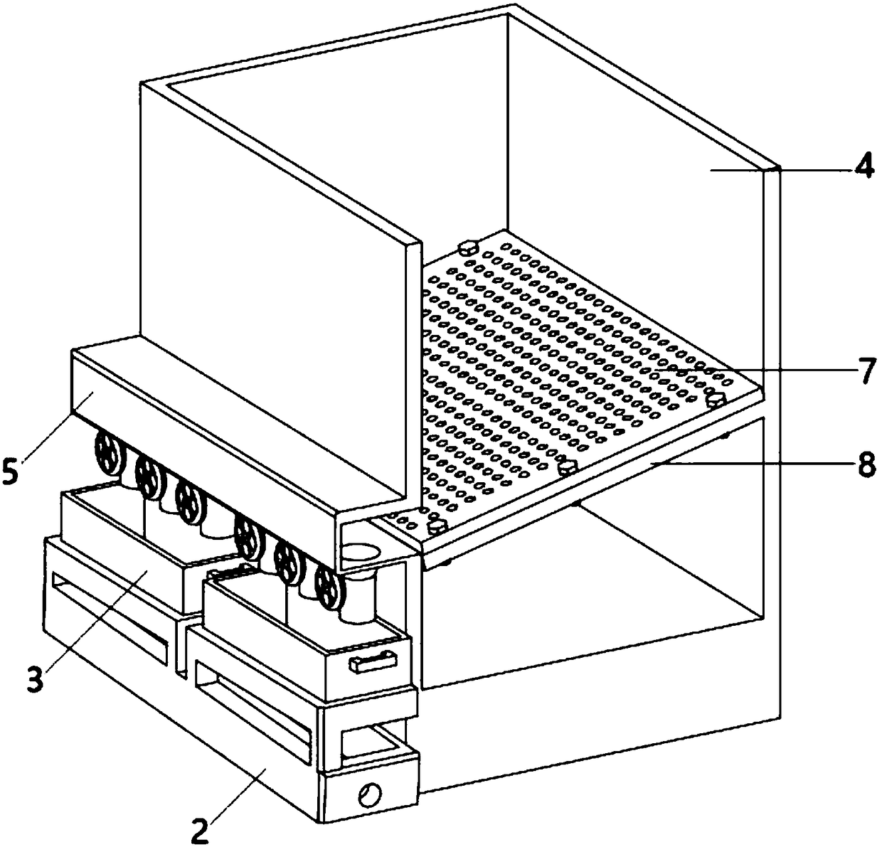
[0029] as attached figure 1 to attach Figure 7 Shown:

[0030] The present invention provides an easy-to-clean heat treatment quenching pool, including: a device body 1, a circulating liquid discharge tank 2, a slag removal box placement frame 201, a slag removal box 3, a quenching pool 4, a slag collection tank 5, and a slag discharge pipeline 501 , a circulating cooling liquid inlet pipe 6, a filter plate 7 and a filter plate mounting frame 8; the main body of the device body 1 is set as a quenching pool 4; the bottom end of one side wall of the quenching pool 4 is provided with a circulation drain 2; the upper side of the circulating liquid drainage tank 2 is provided with a slag removal box placement frame 201; the top of the slag removal box placement frame 201 is embedded with a slag removal box 3; the quenching above the slag removal box 3 A slag collection tank 5 is also arranged correspondingly on the side wall of the pool 4; a slag discharge pipe 501 is provided o...


PUM


Abstract

The invention provides an easily cleaned thermal treatment quenching tank which comprises a circulation liquid discharge tank, a residue cleaning box and a quenching tank, wherein a residue cleaning box holding rack is arranged on the upper side of the circulation liquid discharge tank; the residue cleaning box is mounted at the top of the residue cleaning box holding rack in an embedded manner; aresidue discharge pipeline is arranged on the lower side of a residue collection tank; a filtering net plate mounting rack is arranged on the inner side of the quenching tank; a filtering net plate is fixed on the filtering net plate mounting rack through bolts. The filtering net plate which is of inclined structural design is arranged in the easily cleaned thermal treatment quenching tank, the filtering net plate is inclined towards the residue collection tank, in addition, and the inclined bottom end of the filtering net plate is arranged at the upper end of the bottom surface of the residue collection tank, so that due to the structure, residues can slide into the inner side the residue collection tank through the inclined filtering net plate through continuous vibration of a coolant,and are further discharged out through the residue discharge pipeline, and the physical residue cleaning effect of residues can be effectively improved.

Description

technical field [0001] The invention relates to the technical field of heat treatment quenching equipment, in particular to an easy-to-clean heat treatment quenching pool. Background technique [0002] Heat treatment refers to a metal thermal processing process in which the chemical composition and structure of the surface or interior of the material are changed by means of heating, heat preservation and cooling in the solid state to obtain the required properties. [0003] Based on the above, the inventors found that the existing heat treatment quenching pool has a relatively traditional and simple structural design, and it is inconvenient to clean, which is easy to waste a lot of time and affects work efficiency. Contents of the invention [0004] The purpose of the present invention is to provide an easy-to-clean heat treatment quenching pool to solve the problems that the structural design proposed in the above-mentioned background technology is relatively traditional ...

Claims


Application Information

Patent Timeline
IPC IPC(8): C21D1/64
CPCC21D1/64Y02P10/20
Inventor 王襄苏平金丽何怡娜徐祖建
Owner HUBEI ZANBO INFORMATION TECH CO LTD
Why Eureka
Try Eureka