Rare earth oxide extraction equipment
A technology of rare earth oxides and extraction equipment, which is applied in solvent extraction, chemical instruments and methods, and improvement of process efficiency, etc., can solve the problems of slow extraction speed, poor extraction effect, and inability to control the proportion of solution well.
- Summary
- Abstract
- Description
- Claims
- Application Information
AI Technical Summary
Problems solved by technology
Method used
Image
Examples
Embodiment 1
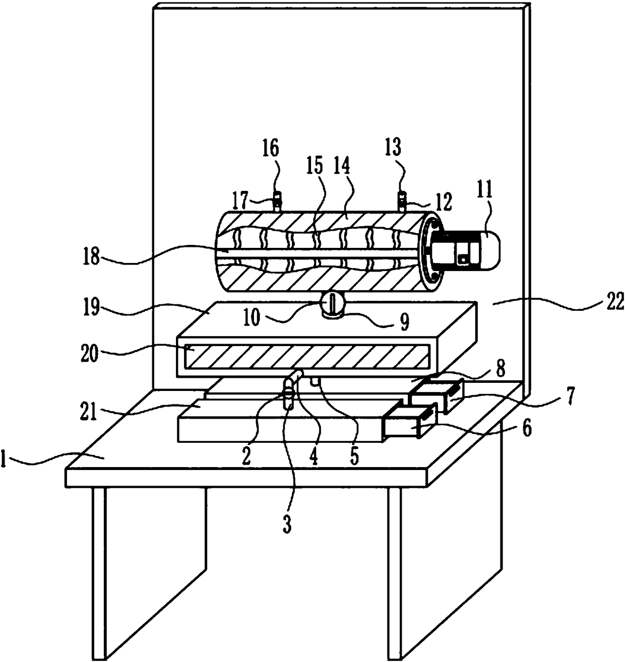
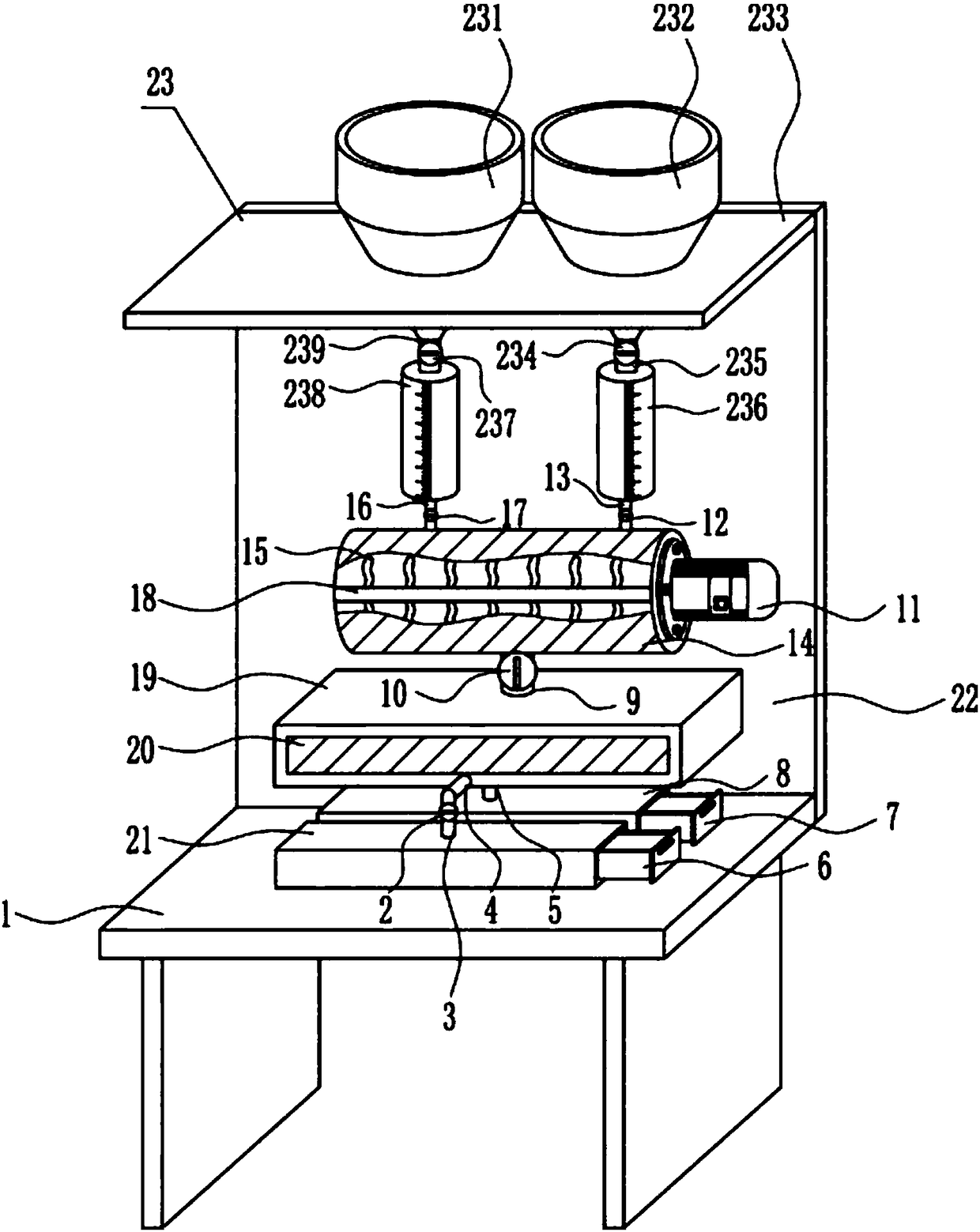
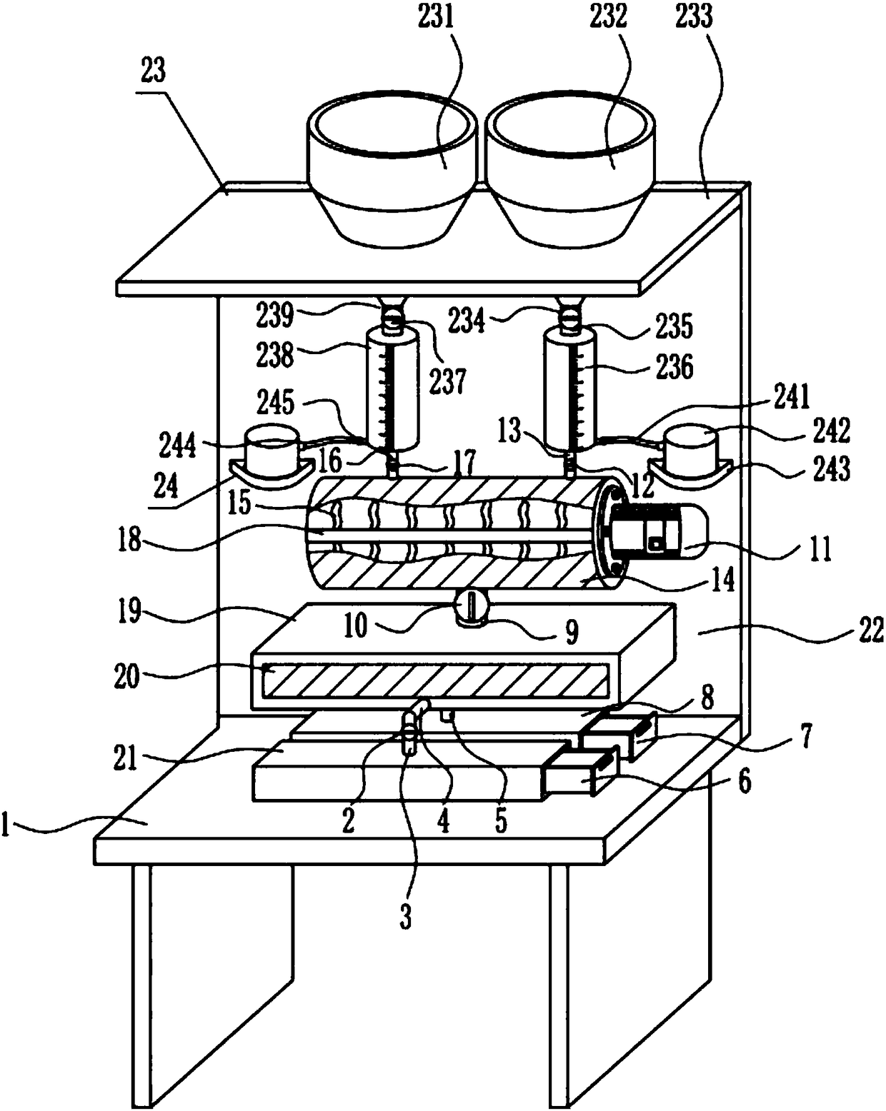
[0038] A kind of rare earth oxide extraction equipment for rare earth waste recycling, such as Figure 1-7 As shown, it includes a placement table 1, a first valve 2, a first liquid outlet pipe 3, a second liquid outlet pipe 4, a third liquid outlet pipe 5, a first storage box 6, a second storage box 7, a first storage box Box 8, fourth liquid outlet pipe 9, second valve 10, motor 11, third valve 12, first liquid inlet pipe 13, mixing cylinder 14, stirring blade 15, second liquid inlet pipe 16, fourth valve 17, Rotating shaft 18, static case 19, first transparent glass 20, second storage box 21 and rear side plate 22, the rear side of placing table 1 is welded with rear side plate 22, and the front side lower part of rear side plate 22 is connected by bolts A mixing cylinder 14 and a static tank 19 are connected, the static tank 19 is located at the bottom of the mixing cylinder 14, a second liquid inlet pipe 16 is welded on the left side of the top of the mixing cylinder 14, ...
Embodiment 2
[0040] A kind of rare earth oxide extraction equipment for rare earth waste recycling, such as Figure 1-7 As shown, it includes a placement table 1, a first valve 2, a first liquid outlet pipe 3, a second liquid outlet pipe 4, a third liquid outlet pipe 5, a first storage box 6, a second storage box 7, a first storage box Box 8, fourth liquid outlet pipe 9, second valve 10, motor 11, third valve 12, first liquid inlet pipe 13, mixing cylinder 14, stirring blade 15, second liquid inlet pipe 16, fourth valve 17, Rotating shaft 18, static case 19, first transparent glass 20, second storage box 21 and rear side plate 22, the rear side of placing table 1 is welded with rear side plate 22, and the front side lower part of rear side plate 22 is connected by bolts A mixing cylinder 14 and a static tank 19 are connected, the static tank 19 is located at the bottom of the mixing cylinder 14, a second liquid inlet pipe 16 is welded on the left side of the top of the mixing cylinder 14, ...
PUM
 Abstract
Description
Claims
Application Information
 - R&D
- Intellectual Property
- Life Sciences
- Materials
- Tech Scout
- Unparalleled Data Quality
- Higher Quality Content
- 60% Fewer Hallucinations
Browse by: Latest US Patents, China's latest patents, Technical Efficacy Thesaurus, Application Domain, Technology Topic, Popular Technical Reports.
© 2025 PatSnap. All rights reserved.Legal|Privacy policy|Modern Slavery Act Transparency Statement|Sitemap|About US| Contact US: help@patsnap.com


