
Novel level crossing bridge in center of road of straight crossing

A level crossing and straight road technology, applied in the field of new bridges at level crossings, can solve the problems of limited road renovation space, congestion, traffic police congestion and other problems, achieve significant production and practical significance, alleviate straight crossing conflicts, and widely popularized and applied Effect

Pending Publication Date: 2018-07-06
MILITARY TRANSPORTATION UNIV PLA
View PDF13 Cites 1 Cited by
  • Summary
  • Abstract
  • Description
  • Claims
  • Application Information

AI Technical Summary

Problems solved by technology

[0002] At present, urban traffic is increasingly congested. Among them, for level crossings in cities (that is, intersections where two roads intersect each other on the same plane, that is, road intersections), vehicles traveling straight at crossings in different directions will suffer from vehicle stagnation, traffic accidents, etc. And other reasons, it is easy to form the cross conflict problem of vehicles driving at the level crossing, which makes the traffic police at the level crossing congested, seriously affecting the safe and smooth driving of the road
[0003] In order to alleviate the traffic congestion at level crossings, the usual methods are: widening the intersection, increasing the number of driving lanes, and building large-scale interchange bridges. However, these methods are limited by the layout of urban roads in my country. Due to limited renovation space and high land prices, it cannot be effectively applied and implemented, and it cannot effectively alleviate the crossing conflicts of vehicles going straight in different directions at urban level crossings.

Method used


Image

  • Novel level crossing bridge in center of road of straight crossing
  • Novel level crossing bridge in center of road of straight crossing
  • Novel level crossing bridge in center of road of straight crossing

Examples


Embodiment Construction

[0045] In order to enable those skilled in the art to better understand the solution of the present invention, the present invention will be further described in detail below in conjunction with the accompanying drawings and embodiments.

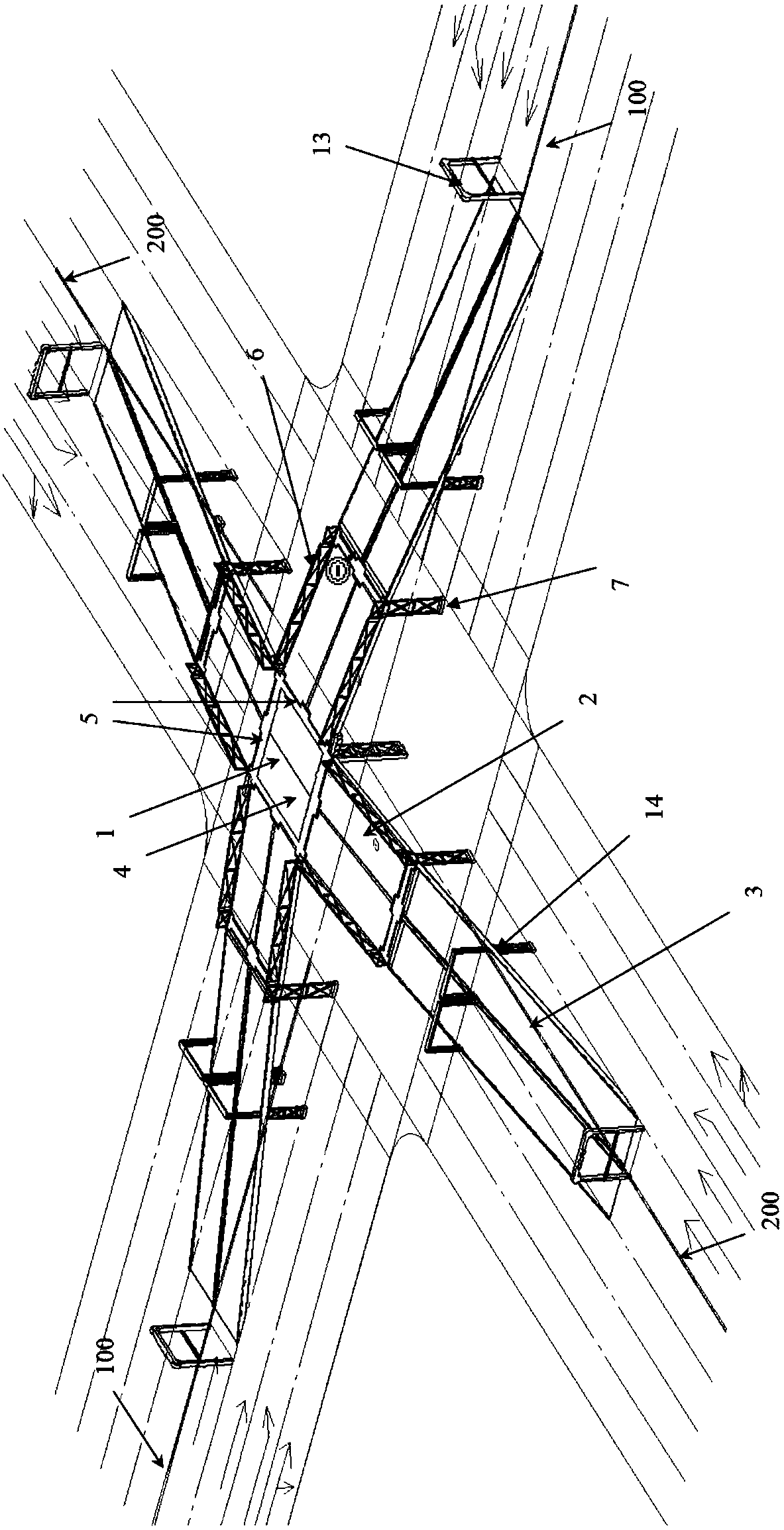
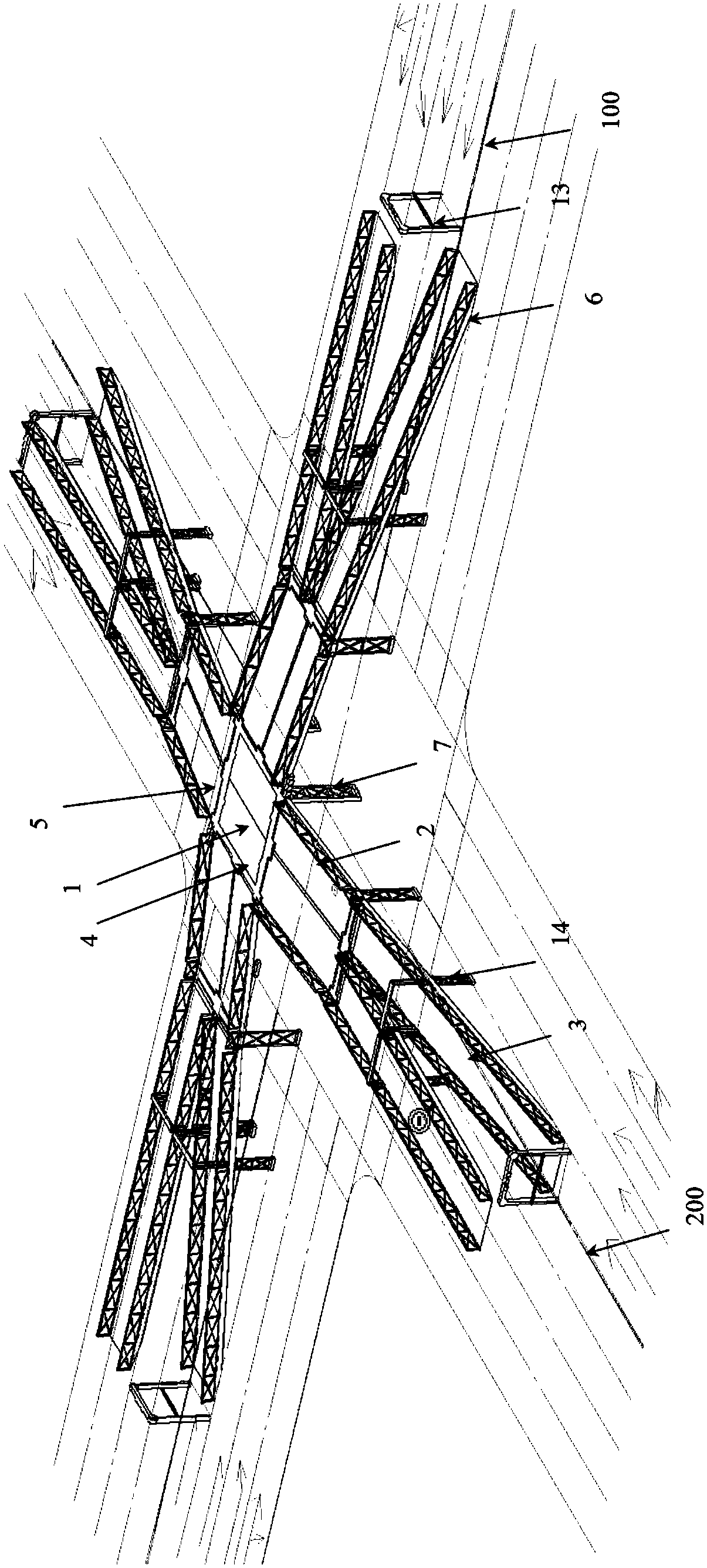
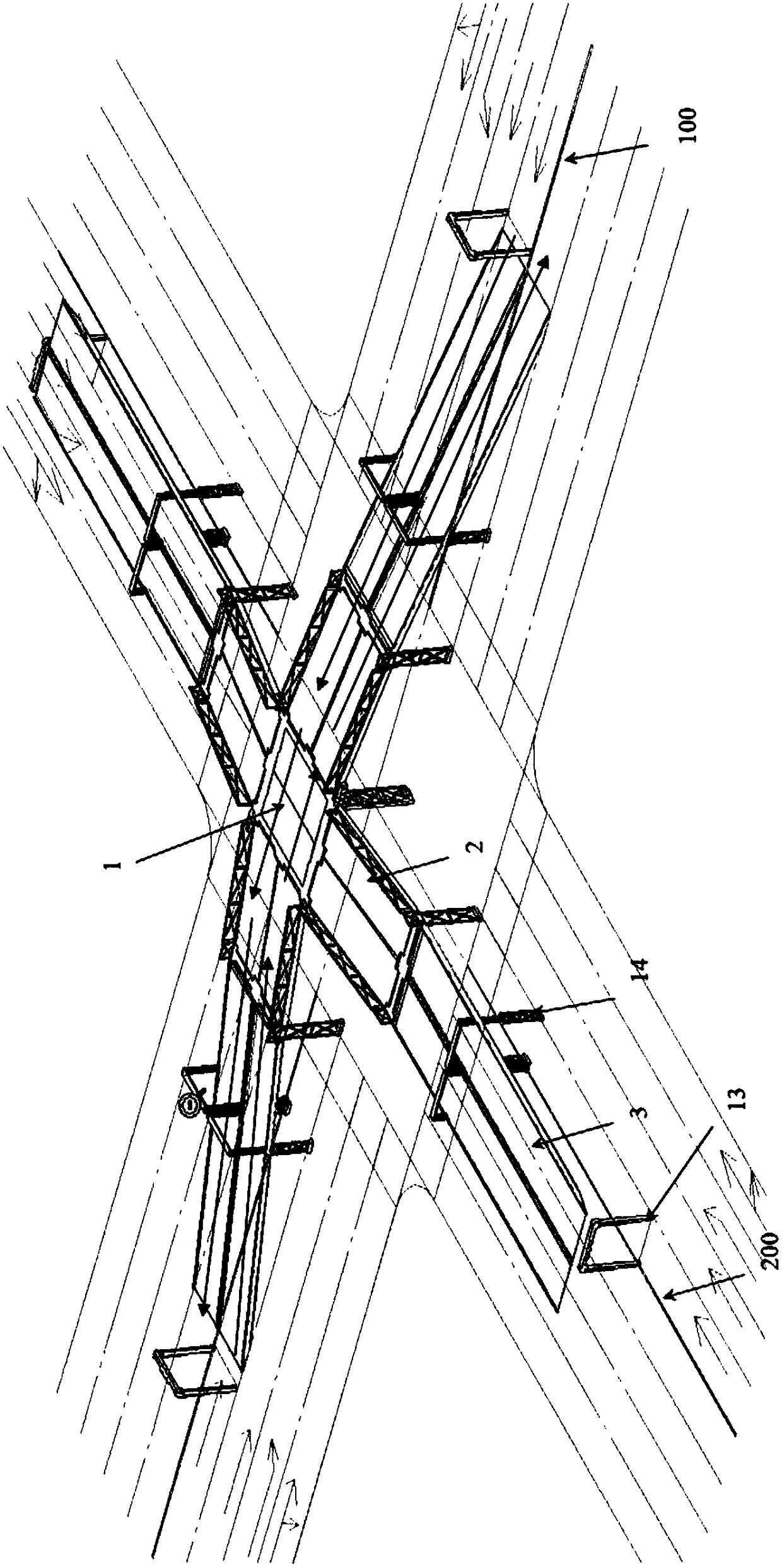
[0046] see Figure 1 to Figure 5 , the present invention provides a new type of bridge applied to a level crossing where the straight crossing lane is in the center of the road, and it is specifically applied to the scene of a level crossing where the straight crossing is in the center of the road (that is, the position next to the center line of the road), specifically includes a fixed platform 1 located above the road;

[0047] The left and right ends of the fixed platform 1 are respectively connected with two sets of transversely distributed approach bridge combinations;

[0048] The front and rear ends of the fixed platform 1 are respectively connected with two sets of longitudinally distributed approach bridge combinations;

[0049] E...


PUM


Abstract

The invention discloses a novel level crossing bridge in the center of a road of a straight crossing. The novel level crossing bridge is arranged on a straight crossing and comprises a fixing platform(1), wherein the fixing platform (1) is positioned above a road; the left end and the right end of the fixing platform (1) are respectively connected with two sets of approach bridges which are distributed transversely; the front end and the rear end of the fixing platform (1) are respectively connected with two sets of approach bridges which are distributed longitudinally; each set of the approach bridges comprise an upper approach bridge (2) and a lower approach bridge (3); the inner side end of each upper approach bridge (2) is connected with the fixing platform (1); the outer side end ofeach upper approach bridge (2) is connected with the inner side end of lower approach bridge (3); the outer side end of each lower approach bridge (3) is connected with the pavement of a horizontal road. By adopting the novel level crossing bridge, the problem of crossing collision of vehicles running in directions at a level crossing of a city can be effectively alleviated, the traffic burden ofthe level crossing can be alleviated, and safe and smooth traffic can be ensured.

Description

technical field [0001] The invention relates to the technical field of bridges, in particular to a new type of bridge applied to level crossings where the straight crossing is in the middle of the road. Background technique [0002] At present, urban traffic is increasingly congested. Among them, for level crossings in cities (that is, intersections where two roads intersect each other on the same plane, that is, road intersections), vehicles traveling straight at crossings in different directions will suffer from vehicle stagnation, traffic accidents, etc. Reasons such as, easily form the intersection conflict problem of vehicle running at level crossing place, make the traffic police congestion at level crossing place, have had a strong impact on the safety of road. [0003] In order to alleviate the traffic congestion at level crossings, the usual methods are: widening the intersection, increasing the number of driving lanes, and building large-scale interchange bridges. ...

Claims


Application Information

Patent Timeline
Patent Type & Authority Applications(China)
IPC IPC(8): E01C1/04E01D15/02
CPCE01C1/04E01D15/02Y02A30/60
Inventor 朱诗顺李振孙燕
Owner MILITARY TRANSPORTATION UNIV PLA
Learn More