Underground continuous wall pipeline in-situ protection construction method

An underground diaphragm wall and pipeline technology, which is applied in the field of engineering technology and science, can solve the problems of large impact on project construction period, heavy coordination workload, and no obstacles, etc., so as to solve the problem of ground wall framing and translation, save construction cost, shorten The effect of project duration

Inactive Publication Date: 2018-07-06
CHINA RAILWAY SHANGHAI ENGINEERING BUREAU GROUP CO LTD +1
View PDF5 Cites 19 Cited by
  • Summary
  • Abstract
  • Description
  • Claims
  • Application Information

AI Technical Summary

Problems solved by technology

[0002] At present, the construction of underground diaphragm wall is one of the most commonly used enclosure structure construction methods for deep foundation pit engineering in urban construction projects. However, during the construction of the enclosure structure, the construction of underground diaphragm walls is often restricted by urban municipal pipelines At the same time, because the traditional underground diaphragm wall construction can only be done straight up and down, and there must be no obstacles when forming the trench, and soil excavation cannot be carried out under the municipal pipeline, so the construction unit often needs to relocate a large number of Underground pipelines; in addition, the relocation of underground pipelines involves many property rights units, a large coordination workload, a long time, and a great impact on the project schedule, which is likely to cause waste of manpower, material resources, and financial resources. The construction method of in-situ protection of pipelines can realize Under the condition of no relocation, carry out the construction of the underground diaphragm wall, and ensure the safety of the pipeline as well as the quality and progress of the construction

Method used


Image

  • Underground continuous wall pipeline in-situ protection construction method
  • Underground continuous wall pipeline in-situ protection construction method
  • Underground continuous wall pipeline in-situ protection construction method

Examples


Embodiment Construction

[0035] The present invention will be further described below in conjunction with accompanying drawing, and the structure and principle of this device are very clear to those skilled in the art. It should be understood that the specific embodiments described here are only used to explain the present invention, not to limit the present invention.

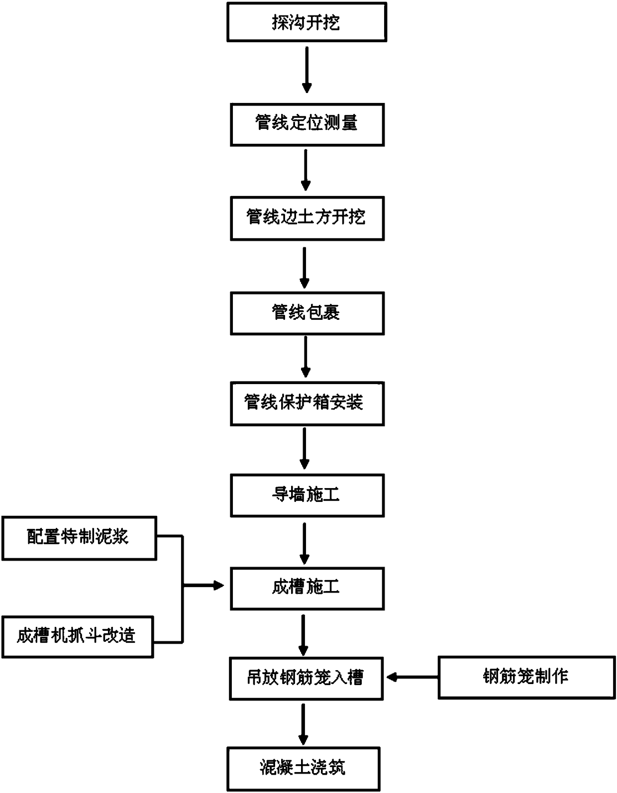
[0036] see Figure 1-8 , a method for in-situ protection construction of underground diaphragm wall pipelines, the method is specifically as follows:

[0037] A. Trench excavation: According to the pipeline 1-2 distribution map, the pipeline trench excavation is carried out, and the type, direction, buried depth and width of the pipeline are initially ascertained;

[0038] B. Pipeline positioning measurement: use a total station and a steel ruler to accurately measure and locate the buried depth, width, height, upper and lower surface elevations and direction of the pipeline;

[0039] C. Excavation of earthwork beside the pipeline: ...


PUM


Abstract

The invention relates to the engineering technical science, and in particular to an underground continuous wall pipeline in-situ protection construction method. The method comprises the steps of ditchexploration and excavation, pipeline positioning and measuring, pipeline side earth excavation, pipeline wrapping, pipeline protection box installation, guide wall construction, slurry preparation, trenching construction, reinforcing cage manufacturing, reinforcing cage hanging in a groove, and concrete pouring. According to the method, the influence of pipeline transition is avoided, the projectconstruction period is shortened, the construction cost is saved, the underground continuous wall trenching construction of the non-straight-up-straight-down mode is realized, and the technical problem of excavating the soil below the pipeline is solved.

Description

[technical field] [0001] The invention relates to engineering technology science, in particular to a method for in-situ protection construction of underground diaphragm wall pipelines. [Background technique] [0002] At present, the construction of underground diaphragm wall is one of the most commonly used enclosure structure construction methods for deep foundation pit engineering in urban construction projects. However, during the construction of the enclosure structure, the construction of underground diaphragm walls is often restricted by urban municipal pipelines At the same time, because the traditional underground diaphragm wall construction can only be done straight up and down, and there must be no obstacles when forming the trench, and soil excavation cannot be carried out under the municipal pipeline, so the construction unit often needs to relocate a large number of Underground pipelines; in addition, the relocation of underground pipelines involves many propert...

Claims


Application Information

Patent Timeline
Patent Type & Authority Applications(China)
IPC IPC(8): E02D5/18
CPCE02D5/18
Inventor 尹金秋刘习生刘思琼辛宏举缪祥军何陈李绍良黄叶平钱琨
Owner CHINA RAILWAY SHANGHAI ENGINEERING BUREAU GROUP CO LTD
Why Eureka
Try Eureka