
Small hydroelectric generator and installation method
A generator and water conservancy technology, which is applied in the field of small hydraulic generators and installation, and can solve problems such as high indirect costs, many accessories, and large projects
- Summary
- Abstract
- Description
- Claims
- Application Information
AI Technical Summary
Problems solved by technology
Method used
Image

Examples
Embodiment 1
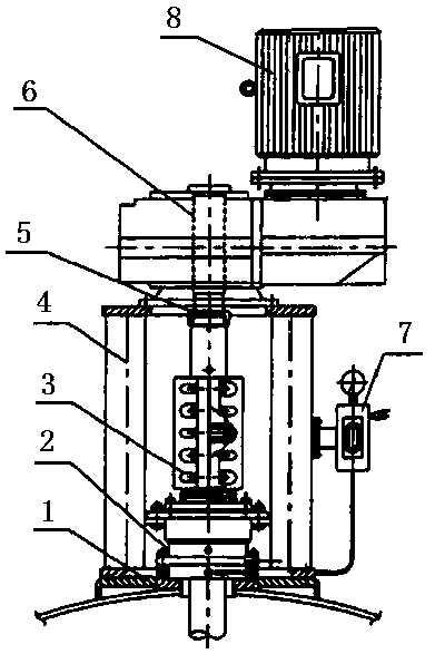
[0019] A small hydraulic generator, which consists of: a base 1, the upper plane of the base is connected to the transmission system through bolts, an impeller 8 is installed in the middle part below the transmission system, and a generator is installed above the transmission system 6. One side of the generator has a wiring port 7, and the side of the transmission system is equipped with a nozzle 5, and an elbow is installed outside the nozzle, and the elbow is fixed to the transmission system. The elbow is connected to the transition joint through the flange.
Embodiment 2
[0021] In the small hydraulic generator described in Embodiment 1, one end of the transition joint is fixed to the pressure water pipe 4, the other end of the pressure water pipe is connected to the water source 3, and a water valve switch 2 is installed on one side of the transition joint.
Embodiment 3
[0023] In the small hydraulic generator described in Embodiment 1, the side of the base has a water outlet 9, the pressure water pipe is placed obliquely with the water source and the transmission system, and the pressure water pipe is at an angle of 45 degrees to the ground .
PUM
 Abstract
Description
Claims
Application Information