
Energy-saving thrust distribution method for dynamic positioning based on improved differential evolution mechanism

A technology of dynamic positioning and improved differential, which is applied in the direction of control/regulation system, instrument, adaptive control, etc., and can solve problems such as thrust restricted area, propeller thrust and angle change rate limitation, difficulty in finding the optimal solution of thrust distribution, etc. Achieve the effects of increasing diversity, improving convergence speed and accuracy, and reasonable thrust distribution

Active Publication Date: 2021-01-05
JIMEI UNIV
View PDF3 Cites 0 Cited by
  • Summary
  • Abstract
  • Description
  • Claims
  • Application Information

AI Technical Summary

Problems solved by technology

[0005] (1) Limited by the power of the driving machine, the thrust generated by each thruster has a maximum value, and the thruster cannot produce a thrust greater than the maximum value
[0006] (2) The rate of change of the propeller thrust and its angle is limited, and it cannot change greatly in a short time
[0007] (3) The azimuth propeller can rotate 360° around its main shaft, but because of the interaction between adjacent propellers, there is a thrust forbidden zone, so it is necessary to set a range of variation for the rotation angle of each propeller
[0013] At present, the main method of ship dynamic positioning thrust allocation is to ignore the energy consumption characteristics of thrust allocation, and it is difficult to find the optimal solution of thrust allocation.

Method used


Image

  • Energy-saving thrust distribution method for dynamic positioning based on improved differential evolution mechanism
  • Energy-saving thrust distribution method for dynamic positioning based on improved differential evolution mechanism
  • Energy-saving thrust distribution method for dynamic positioning based on improved differential evolution mechanism

Examples


Embodiment Construction

[0040] The present invention will be further explained below in conjunction with the accompanying drawings and specific embodiments.

[0041] A brief description of the differential evolution algorithm is as follows:

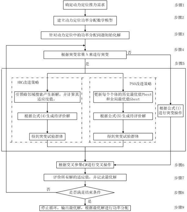
[0042] Mutation: Mutation is a very important link in the reproductive cycle. It randomly selects three parent individuals from the population to produce experimental individuals. In the mutation operation, the experimental individual variable x' i According to the following formula to get:

[0043] x' i =x r1 +F(x r2 -x r3 ) (1)

[0044] where x r1 , x r2 and x r3 is a randomly selected variable and r1≠r2≠r3, F is a scaling factor used to control the total amount of perturbation in the mutation process and improve the convergence speed, and its value range is [0,1].

[0045] Crossover: The crossover operation is similar to the exchange and recombination of two fragments of a gene according to a certain probability to produce offspring individuals. Th...


PUM


Abstract

The invention provides a power positioning energy-saving thrust distribution method based on an improved differential evolution mechanism, which comprises the following steps of: step 1, determining adynamic positioning power demand; step 2, establishing a dynamic positioning power distribution mathematical model; step 3, initializing a solution aiming at the power distribution problem in the power positioning; step 4, selecting a mutation mode according to the mutation constant lambda; step 5, performing the mutation operation; step 6, performing the cross operation; step 7, evaluating the adaptive value of all the solutions, and recoding the optimal solution; step 8, judging whether the termination condition is met or not, and if yes, executing the step 9, otherwise, returning to the step 4; Step 9: stopping the loop, outputting the optimal solution, and performing power allocation according to the optimal solution. According to the invention, the thrust required by the power positioning ship is reasonably distributed to each propeller, on the basis of ensuring the safety of the ship, the energy consumption of the ship and the operation cost of the ship are reduced, and the pollution of the ship is also reduced.

Description

technical field [0001] The invention relates to the field of ship automation, in particular to a dynamic positioning energy-saving thrust distribution method based on an improved differential evolution mechanism. Background technique [0002] The main function of a ship's dynamic positioning system (DPS) is to keep the ship in a desired position or to drive the ship along a specified trajectory. It mainly calculates the total thrust and torque required by the ship in real time according to the deviation between the current position state of the ship and the expected value and the external environment interference, and then calculates the propulsion of each thruster equipped by the ship according to the thrust distribution logic method. The required thrust and its angle will be generated, and the control command will be transmitted to the propeller, and the propeller will generate the required thrust according to the command to complete the positioning of the ship. Therefore...

Claims


Application Information

Patent Timeline
Patent Type & Authority Patents(China)
IPC IPC(8): G05B13/04
CPCG05B13/042
Inventor 吴德烽赵珂顾佳栋
Owner JIMEI UNIV
Learn More